TL;DR
The long-standing bug discussed in the blog (see link above) that impacts the way that certain Mesh objects decay their LODs has been identified and fixed. I will be submitting the patch to Firestorm and other TPVs where applicable and back to the Lab so that (if it is accepted) we can be rid of this pain in the posterior.
Introduction
After having suffered and grumbled at this bug for a long time I decided to bite the bullet and for the first time since about 2009, build and debug the viewer. After a week or so of digging around and working out how V3 viewers hang together, I now have a solution to the problem we observe, but it still needs to go through QA and of course the thing I cannot know...why did it do that? More of that later...The basic problem
Here is the basic problem as we originally observed it.Any mesh object with either 3 or 4 texture faces will crumple earlier than an identically sized mesh with only 2 texture faces.
But in fact it is worse than that (a little).
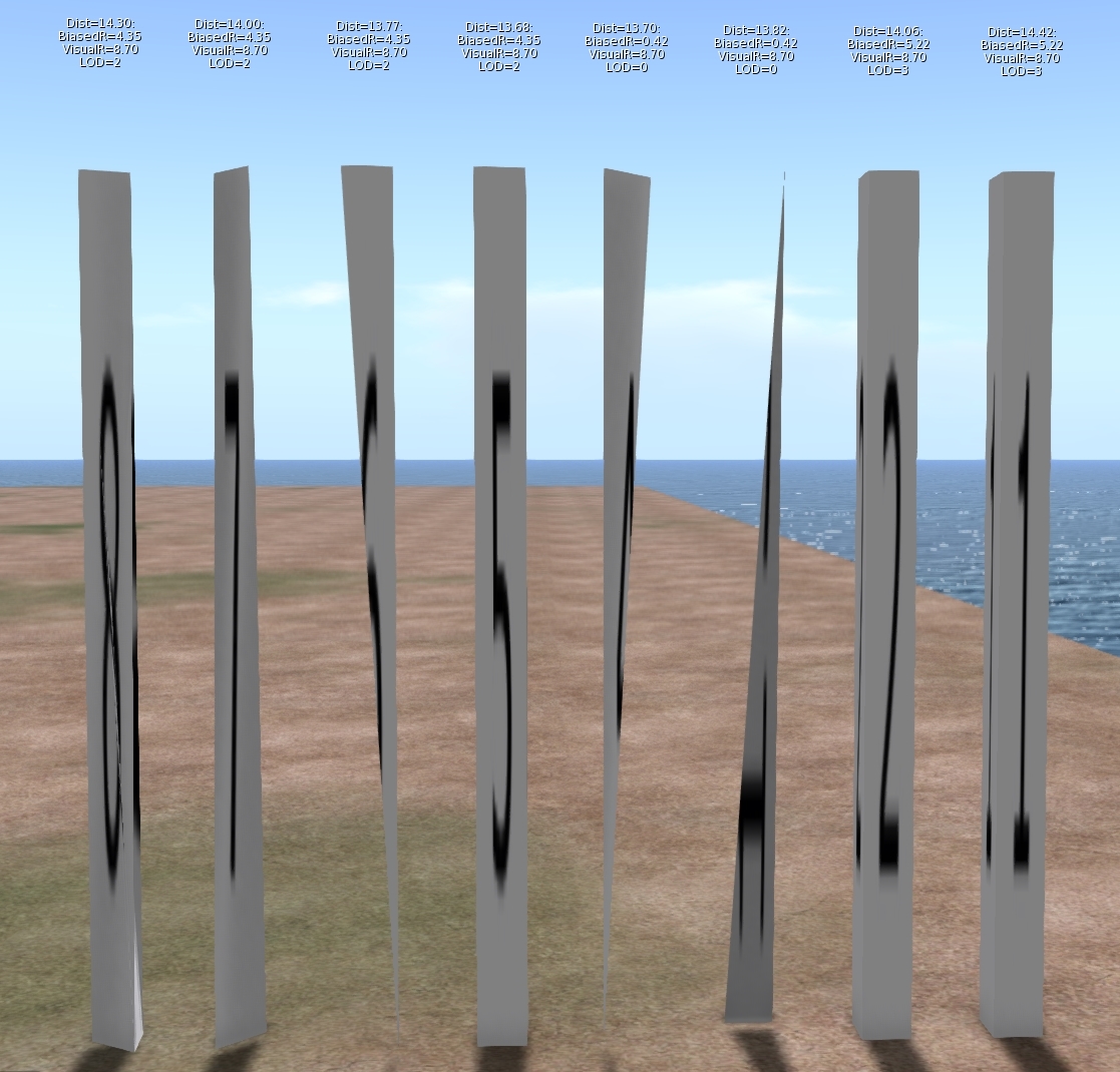
As I dug into this problem it turns out that this is not a problem that affects 3 and 4 materials only, it just affects them worse. Meshes with 5, 6, 7 & 8 material faces will also collapse earlier than the comparable 1 and 2 material versions. The following image will illustrateThe image shows 8 identically sized columns. Under normal circumstances, one would expect these to look identical and change LOD at the same distance from the viewer. The textual display above each shows the following:
Dist: The distance of the object from the viewer.
Biased Radius: An adjusted radius based upon a biasing algorithm, the source of our woes.
Visual Radius: The "True" Radius defined by the bounding box of the object.
LOD: The Level Of Detail currently shown. 3=HIGH, 2=MED, 1=LOW, 0=LOWEST
The display is a bug fix/enhancement of my own and if accepted will appear in a future viewer. It is a change to the existing Render Metadata -> LOD Info which is basically broken on all existing viewers. I should also note that I use the term radius here, because not only is it the term we use inworld when examining the LOD equations, but it is also used in the code, all of which is despite the fact that it is not the radius at all but the long diagonal of the bounding box!
As you can see, Objects 1 & 2 are still at LOD 3, even though their distance from the camera is marginally more than the others. Further scrutiny of the hovering figures shows that the Biased Radius is 5.22 compared to 4.35and 0.42. Objects 3 & 4 have collapsed to LOD 0, with a biased Radius of just 0.42 they had little hope of remaining visible. While all the others have decayed to a slightly withered LOD2.
But why does this happen? To understand this we need a little implementation detail.
What does a mesh look like on the inside?
SL is often criticised and even rubbished for the way it does things, but if I am really honest I have a great deal of admiration for the general architecture. For a system design 15 years ago it has managed to grow and adapt and shown remarkable durability. The code certainly bears many battle scars and the stretch marks of its adolescence glare an angry red under scrutiny but the fact that it has gone from super optimised prims through to industry standard Mesh, growing as and when the technology of its users was best able to adopt it is very impressive.
Second Life has achieved this longevity through a series of "cunning plans" which have extended the capability without altering the infrastructure drastically. all the objects in your inventory have a top level structure which is basically a legacy prim, extensions have been variously grafted on to this but leave behind the traits of the original prims. This means that, even though they are unused, a mesh has a slice, taper and cut setting as well as many others.
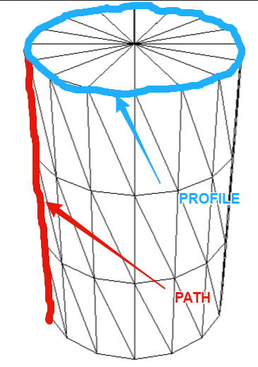
These top level prims also denote what type of prim they are, cube, sphere, cone, etc. and Meshes are no different. The basic shape is determined through two parameters the PATH and the PROFILE. Thus a sphere has a PATH and PROFILE of CIRCLE, while a cylinder has a PATH of LINE and a PROFILE of CIRCLE. Sculpts came along later and are indicated by the presence of a sculpt parameter block on the end of the Prim. Perhaps surprisingly Mesh is denoted as a type of Sculpt with the "SculptType" is set to the value 5 representing Mesh.
This allows the "cunning plan" that the settings for a sculpt can be reused. In a traditional sculpted prim, the SculptID holds the asset server UUID of an image that defines the sculptmap. In a Mesh the same field is used to hold a UUID of the underlying Mesh. It is important to note here that the Mesh that you upload is given this UUID that is the "child" of the Mesh object. You never actually get to see or know the underlying Mesh asset ID inworld.
So we now know that a Mesh is really a legacy prim, denoted as a sculpt, whose map is redirected to a Mesh defintion. So let's see where it goes wrong.
LODScaleBias and the legacy impact.
My first task in trying to fix this bug was to start to map out the viewer. It has been at least 6 years since I last looked at the viewer code and back then I was only really building it for my own purposes. The code has all the hallmarks of mature and much patched and extended code and is a bit of a rat's nest at times, but nestled deep inside the nest is a function simply called calcLod()
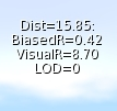
This function, along with the name, also was home to the output for the Render Metadata->LOD Info function.The Render Metadata services are a set of great tools for builders and developers who are trying to understand a problem, those who have read this blog in the past will be well aware of the physics display. The LOD Info display has been a bugbear of mine for some time, I have never been able to work out what it was displaying, It would show a number that would typically not change with the LOD display and was to all intents and purposes useless. It turns out that is exactly what it is. At some point in the past it appears to have been borrowed for some other purpose and upon examination had nothing to do with the LOD at all. The damning evidence was a commented out remnant of the original call. My first "fix" of the expedition was, therefore, to make this function more useful, the new display is shown on the left. I will be submitting that patch separately.
Back to our friend calcLOD().
I won't post the code here, it is too long but the function does what you would expect it to do given its name but the devil is in the detail.
BOOL LLVOVolume::calcLOD()
{
F32 radius;
F32 distance;
if (mDrawable->isState(LLDrawable::RIGGED))
{
// if this is rigged set the radius to that of the avatar
}
else
{
distance = mDrawable->mDistanceWRTCamera;
radius = getVolume() ? getVolume()->mLODScaleBias.scaledVec(getScale()).length() : getScale().length();
}
.....etc etc
}
There are a couple of interesting diversions in this function, the first we covered above, the second is a special clause for rigged attachments which deliberately adjusts their LOD scale to be that of the avatar that is wearing them. This is the subject of a Jira and is likely to come under scrutiny in the current quest to improve complexity determination.
 However it is the code in bold and further highlighted that we care about. What is this LODScaleBias? Our amended LODInfo display proves that this is the culprit. The BiasedRadius of a 3 face Mesh is shown on the left and can be compared to the same mesh with 6 material faces shown in the example above. 0.42 when the true radius is 8.7, no wonder the thing crumbles.
 Digging deeper we can identify where the LODScaleBias vector is initialised.
BOOL LLVolume::generate(){
...snip...
mLODScaleBias.setVec(0.5f, 0.5f, 0.5f);
...snip...
if (path_type == LL_PCODE_PATH_LINE && profile_type == LL_PCODE_PROFILE_CIRCLE)
{ //cylinders don't care about Z-Axis
mLODScaleBias.setVec(0.6f, 0.6f, 0.0f);
}
else if (path_type == LL_PCODE_PATH_CIRCLE)
{
mLODScaleBias.setVec(0.6f, 0.6f, 0.6f);
}
...
So here we have it.
"Cylinders don't care about Z-Axis"
The code above sets up the bias. The default bias is <0.5, 0.5, 0.5> and I'm feeling rather stupid now because having said previously that Radius is not really the radius...if you take the long diagonal and half it then of course you do have the radius (the radius of a sphere that encloses the bounding box, at least.) We then get to the code in bold red. Here we find that if the legacy prim has a linear path and a circular profile then it must be a cylinder,
The image to the left shows my hand drawn annotation of what those two parameters mean. Anyone who worked with prims will most likely understand the terms.This does pose a couple of questions, the most obvious of which is:-
"Cylinders don't care about Z-Axis" WHY!!!!?
There seems no logic to explain why a cylinder would be set to LOD quicker. Clearly, when used as a column it results in a high number of long thin triangles but does that really warrant such punishment? I have enquired with a couple of Lindens to see if we can get some clarification on the history of this.
Noting the <0.6, 0.6, 0.0> when applied to our example mesh columns give a Radius of 0.42 we can confirm that this is , as had been suspected, how out poor Meshes are being evaluated, and so the second most obvious question is:-
Why is my Mesh arbitrarily being branded as a cylinder?
Again there seems no rhyme nor reason to the 3 and 4 material face meshes being treated this way. If the lab responds with an answer to either of these I will post a blog to share the info.
Having determined why we have this issue we need to go and find out where. At first, this seemed a daunting task. Somewhere in all the viewer code was a single line or two that was initialising these parameters incorrectly. I decided to start at the very beginning. The beginning for any asset is when it gets sent from the server to the client, a little hunting and we find a function that is called to process and unpack an update message for an object. In this code, I found the point at which the parameters are unpacked and placed some additional logging to print out the settings.
Lo and behold the viewer is not to blame at all. The Object is already tainted before it arrives. This means that something is happening on the server and it would seem to be deliberate.
How can we assume it is on the server?
We have in previous blogs examined the Mesh Asset upload format and can note that there is no room in there for the legacy parameters. Moreover, that asset is the data that is referenced as the "SculptId". The Containing/parent prim is different, it is created on the server side, presumably during the validation of the upload process, the initilisation of the parent object must be assigning default values based on certain consistent criteria and as such results in the problem. As with the above, I have asked the lab whether they can confirm the reason for this, primarily so that we can understand if there are any side effects.
Having noted that Meshes are already tainted I added code to list out the types of Mesh and using a conveniently empty sim on the beta grid Aditi I created my series of 8 "identical" meshes.
the result can be summarised as follows.
|
# faces
|
PATH
|
PROFILE
|
BIAS
|
|
1
|
CIRCLE
|
CIRCLE_HALF
|
<0.6,0.6,0.6>
|
|
2
|
CIRCLE
|
CIRCLE
|
<0.6,0.6,0.6>
|
|
3
|
LINE
|
CIRCLE
|
<0.6,0.6,0.0>
|
|
4
|
LINE
|
CIRCLE
|
<0.6,0.6,0.0>
|
|
5
|
LINE
|
EQUALTRI
|
<0.5,0.5,0.5>
|
|
6
|
LINE
|
SQUARE
|
<0.5,0.5,0.5>
|
|
7
|
LINE
|
SQUARE
|
<0.5,0.5,0.5>
|
|
8
|
LINE
|
SQUARE
|
<0.5,0.5,0.5>
|
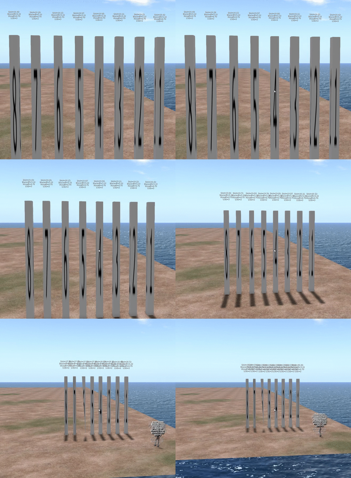
That is the end really. With the fix in place the Meshes quickly resolve and the new LOD Info display confirms that the Bias is no longer unfairly having some meshes. As for side-effects, we only modify at run time, and nothing is ever saved back to the server. Moreover I have implemented this to be configurable and should any issues arise it could be easily disabled.
So what next?
I am no cleaning up the code to remove or at lesat comment out any of the debug logging I used. I will then create a submit a patch to Firestorm. Having spoken to Oz Linden, I have been asked to sign a contribution agreement, this is a form that protects the Lab (and thus all of us) from me giving code and then claiming some licensing later.Once I have that in place the lab can accept my change and would then consider it. So that means that subject to QA and testing to follow hopefully we can put this bug to rest once and for all.
It leaves a few loose ends.
Why does a Cylinder ignore the Z? I just want to know.Why does the server do this and will/should the server-side get fixed?
Would fixing this on the server make a difference to the SL Map
That's all for now, I shall leave you with an animation of the FIX in action,
Love
Beq
x


No comments:
Post a Comment