Sunday, 9 October 2016

Not as simple as it looks...

A little bad news

In my last post on "bug hunting", I talked about the LOD decay issue and a potential fix. I said in the blog that "subject to QA" it would be coming to you soon and sure enough QA found an issue. It turns out, rather a large issue given that as a result of my fix a lot of mesh textures get utterly corrupted. Needless to say, that patch was backed out. Thanks to Ansariel Hillier and Whirly Fizzle from the Firestorm development team for spotting and doing some initial troubleshooting of it for me while I was overseas.

It is not all bad news

The good news is that I have submitted a new patch that uses a completely different method. It is a method that I shied away from first time as I felt it was too close to the critical path, i.e. a part of the code that has significant impact on the overall performance, and chose to make changes far earlier. I am happier with the new solution, it is simpler, more elegant in some ways, and overall improves the performance ever so slightly by avoiding some convoluted checks when calculating the LOD for Mesh.

This patch has also highlighted the rather bizarre dependency that a mesh has on the legacy prim definitions and adds weight to my request for documentation on why this is done. Once I have cleared a few other loose ends up I may well circle round and have a look at this again.

On a related note. Complexity and confusion

With the recent introduction of complexity limits to the viewer has confused some people and highlighted certain bad practices in Mesh creation. However, due to a range of different "features" it is still not really as reliable as anyone would hope. Part of this is down to the fact the rigged mesh does not have its LOD calculated in the same way. 

In fact, for worn, rigged mesh the LOD is not based upon the radius of the object but is instead tied to the bounding box of the avatar that wears it. This is a quite deliberate choice, explicitly mentioned in the viewer code,  and means that if you wear a Mesh body and Mesh head and Mesh hands, that they ultimately LOD swap at the same time, rather than the hands decaying first (being the smallest) then the head and later the body but it also means that the complexity calculations need to consider this (which they do not at present). This means that those super high poly onion skin mesh head that melt down your graphics card in a busy sim, are only getting a complexity score based on the apparent scale and yet they are visible based on a much larger scale. Once you realise this...you can then read my Jira here because it is actually worse than that, rigged meshes are being given a far far easier ride that they deserve.

All this being said, it is what it is and changing this stuff is hard because it breaks things. So the Lab are looking at pulling together all the oddities in the LOD and complexity calculations and reviewing them to see what if anything can be done to make the complexity numbers more meaningful and usable. There is no timescale for this, just an intention to review things at the moment. I for one will be keeping a keen eye on progress.

Love 

Beq
x

Saturday, 1 October 2016

Bug hunting - Fixing an ancient LOD issue

Those of you who may have read my blog post in July, "Tell your friends - An old bug that people really ought to know about." might be interested to know that I have made a lot of progress towards fixing it.

TL;DR

The long-standing bug discussed in the blog (see link above) that impacts the way that certain Mesh objects decay their LODs has been identified and fixed. I will be submitting the patch to Firestorm and other TPVs where applicable and back to the Lab so that (if it is accepted) we can be rid of this pain in the posterior.

Introduction

After having suffered and grumbled at this bug for a long time I decided to bite the bullet and for the first time since about 2009, build and debug the viewer. After a week or so of digging around and working out how V3 viewers hang together, I now have a solution to the problem we observe, but it still needs to go through QA and of course the thing I cannot know...why did it do that? More of that later...

The basic problem

Here is the basic problem as we originally observed it.

Any mesh object with either 3 or 4 texture faces will crumple earlier than an identically sized mesh with only 2 texture faces.

But in fact it is worse than that (a little).

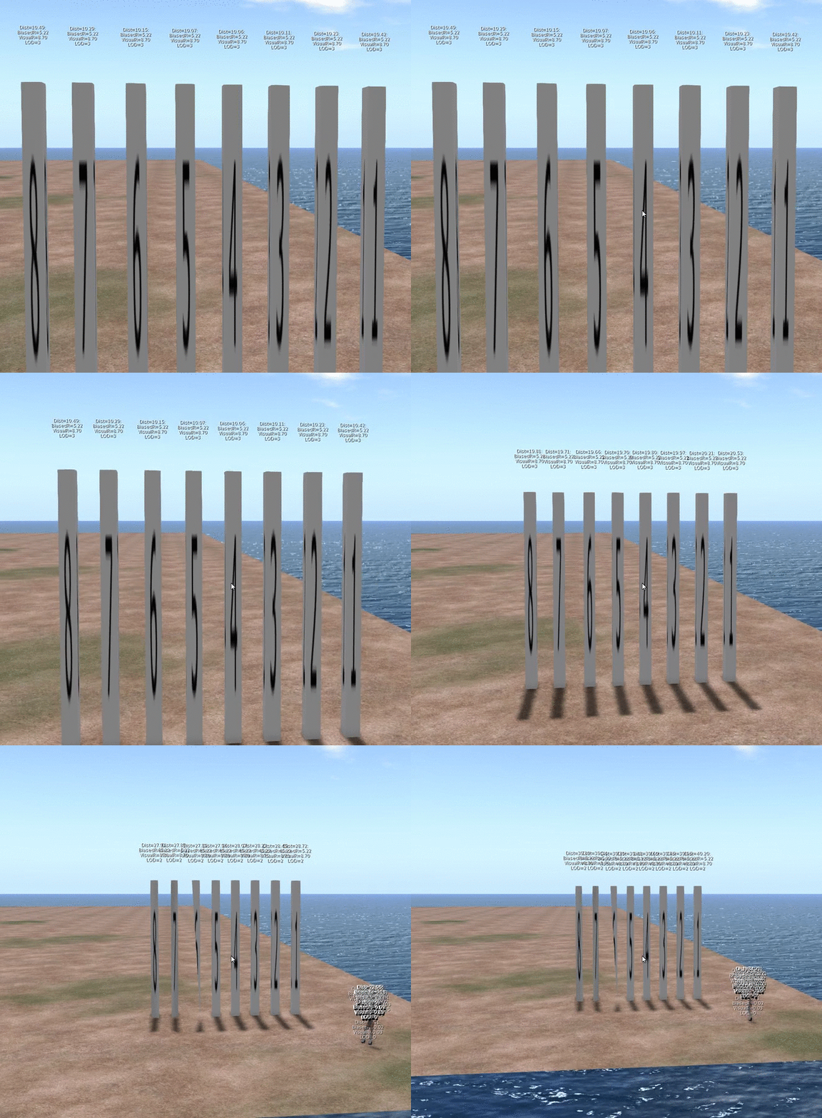
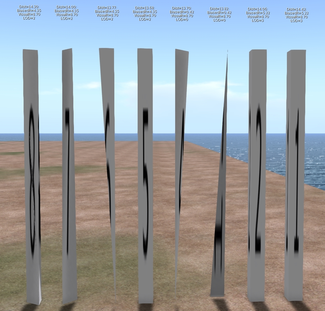
As I dug into this problem it turns out that this is not a problem that affects 3 and 4 materials only, it just affects them worse. Meshes with 5, 6, 7 & 8 material faces will also collapse earlier than the comparable 1 and 2 material versions. The following image will illustrate

The image shows 8 identically sized columns. Under normal circumstances, one would expect these to look identical and change LOD at the same distance from the viewer. The textual display above each shows the following:
Dist:                   The distance of the object from the viewer.
Biased Radius:   An adjusted radius based upon a biasing algorithm, the source of our woes.
Visual Radius:    The "True" Radius defined by the bounding box of the object.
LOD:                  The Level Of Detail currently shown. 3=HIGH, 2=MED, 1=LOW, 0=LOWEST

The display is a bug fix/enhancement of my own and if accepted will appear in a future viewer. It is a change to the existing Render Metadata -> LOD Info which is basically broken on all existing viewers. I should also note that I use the term radius here, because not only is it the term we use inworld when examining the LOD equations, but it is also used in the code, all of which is despite the fact that it is not the radius at all but the long diagonal of the bounding box!

As you can see, Objects 1 & 2 are still at LOD 3, even though their distance from the camera is marginally more than the others. Further scrutiny of the hovering figures shows that the Biased Radius is 5.22 compared to 4.35and 0.42. Objects 3 & 4 have collapsed to LOD 0, with a biased Radius of just 0.42 they had little hope of remaining visible. While all the others have decayed to a slightly withered LOD2.

But why does this happen? To understand this we need a little implementation detail.

What does a mesh look like on the inside?

SL is often criticised and even rubbished for the way it does things, but if I am really honest I have a great deal of admiration for the general architecture. For a system design 15 years ago it has managed to grow and adapt and shown remarkable durability. The code certainly bears many battle scars and the stretch marks of its adolescence glare an angry red under scrutiny but the fact that it has gone from super optimised prims through to industry standard Mesh, growing as and when the technology of its users was best able to adopt it is very impressive. 

Second Life has achieved this longevity through a series of "cunning plans" which have extended the capability without altering the infrastructure drastically. all the objects in your inventory have a top level structure which is basically a legacy prim, extensions have been variously grafted on to this but leave behind the traits of the original prims. This means that, even though they are unused, a mesh has a slice, taper and cut setting as well as many others.

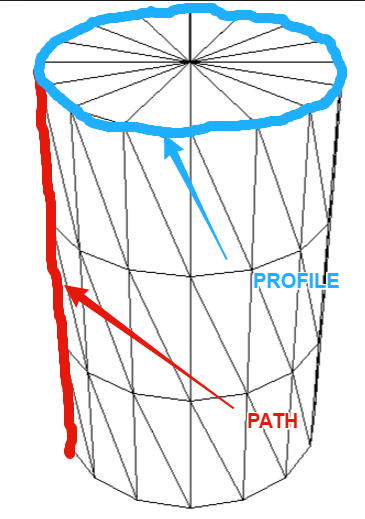
These top level prims also denote what type of prim they are, cube, sphere, cone, etc. and Meshes are no different. The basic shape is determined through two parameters the PATH and the PROFILE. Thus a sphere has a PATH and PROFILE of CIRCLE, while a cylinder has a PATH of LINE and a PROFILE of CIRCLE. Sculpts came along later and are indicated by the presence of a sculpt parameter block on the end of the Prim. Perhaps surprisingly Mesh is denoted as a type of Sculpt with the "SculptType" is set to the value 5 representing Mesh.

This allows the "cunning plan" that the settings for a sculpt can be reused. In a traditional sculpted prim, the SculptID holds the asset server UUID of an image that defines the sculptmap. In a Mesh the same field is used to hold a UUID of the underlying Mesh. It is important to note here that the Mesh that you upload is given this UUID that is the "child" of the Mesh object. You never actually get to see or know the underlying Mesh asset ID inworld.

So we now know that a Mesh is really a legacy prim, denoted as a sculpt, whose map is redirected to a Mesh defintion. So let's see where it goes wrong.

LODScaleBias and the legacy impact.

My first task in trying to fix this bug was to start to map out the viewer. It has been at least 6 years since I last looked at the viewer code and back then I was only really building it for my own purposes. The code has all the hallmarks of mature and much patched and extended code and is a bit of a rat's nest at times, but nestled deep inside the nest is a function simply called calcLod()
This function, along with the name, also was home to the output for the Render Metadata->LOD Info function.

The Render Metadata services are a set of great tools for builders and developers who are trying to understand a problem, those who have read this blog in the past will be well aware of the physics display. The LOD Info display has been a bugbear of mine for some time, I have never been able to work out what it was displaying, It would show a number that would typically not change with the LOD display and was to all intents and purposes useless. It turns out that is exactly what it is. At some point in the past it appears to have been borrowed for some other purpose and upon examination had nothing to do with the LOD at all. The damning evidence was a commented out remnant of the original call. My first "fix" of the expedition was, therefore, to make this function more useful, the new display is shown on the left. I will be submitting that patch separately.

Back to our friend calcLOD().
I won't post the code here, it is too long but the function does what you would expect it to do given its name but the devil is in the detail.

BOOL LLVOVolume::calcLOD()
{
F32 radius;
F32 distance;

if (mDrawable->isState(LLDrawable::RIGGED))
{
// if this is rigged set the radius to that of the avatar              
}
else
{
distance = mDrawable->mDistanceWRTCamera;
radius = getVolume() ? getVolume()->mLODScaleBias.scaledVec(getScale()).length() : getScale().length();
}
.....etc etc
}

There are a couple of interesting diversions in this function, the first we covered above, the second is a special clause for rigged attachments which deliberately adjusts their LOD scale to be that of the avatar that is wearing them. This is the subject of a Jira and is likely to come under scrutiny in the current quest to improve complexity determination.
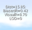
However it is the code in bold and further highlighted that we care about. What is this LODScaleBias? Our amended LODInfo display proves that this is the culprit. The BiasedRadius of a 3 face Mesh is shown on the left and can be compared to the same mesh with 6 material faces shown in the example above. 0.42 when the true radius is 8.7, no wonder the thing crumbles. 

Digging deeper we can identify where the LODScaleBias vector is initialised. 
BOOL LLVolume::generate(){
...snip...
    mLODScaleBias.setVec(0.5f, 0.5f, 0.5f);
...snip...        
    if (path_type == LL_PCODE_PATH_LINE && profile_type == LL_PCODE_PROFILE_CIRCLE)
    { //cylinders don't care about Z-Axis
        mLODScaleBias.setVec(0.6f, 0.6f, 0.0f);
    }
    else if (path_type == LL_PCODE_PATH_CIRCLE) 
    {    
        mLODScaleBias.setVec(0.6f, 0.6f, 0.6f);
    }

 ...
So here we have it.

"Cylinders don't care about Z-Axis"

The code above sets up the bias. The default bias is <0.5, 0.5, 0.5> and I'm feeling rather stupid now because having said previously that Radius is not really the radius...if you take the long diagonal and half it then of course you do have the radius (the radius of a sphere that encloses the bounding box, at least.) We then get to the code in bold red. Here we find that if the legacy prim has a linear path and a circular profile then it must be a cylinder, 
The image to the left shows my hand drawn annotation of what those two parameters mean. Anyone who worked with prims will most likely understand the terms.

This does pose a couple of questions, the most obvious of which is:-
"Cylinders don't care about Z-Axis" WHY!!!!?

There seems no logic to explain why a cylinder would be set to LOD quicker. Clearly, when used as a column it results in a high number of long thin triangles but does that really warrant such punishment? I have enquired with a couple of Lindens to see if we can get some clarification on the history of this.

Noting the <0.6, 0.6, 0.0> when applied to our example mesh columns give a Radius of 0.42 we can confirm that this is , as had been suspected, how out poor Meshes are being evaluated, and so the second most obvious question is:-
Why is my Mesh arbitrarily being branded as a cylinder? 
Again there seems no rhyme nor reason to the 3 and 4 material face meshes being treated this way. If the lab responds with an answer to either of these I will post a blog to share the info.

Having determined why we have this issue we need to go and find out where. At first, this seemed a daunting task. Somewhere in all the viewer code was a single line or two that was initialising these parameters incorrectly. I decided to start at the very beginning. The beginning for any asset is when it gets sent from the server to the client, a little hunting and we find a function that is called to process and unpack an update message for an object. In this code, I found the point at which the parameters are unpacked and placed some additional logging to print out the settings. 

Lo and behold the viewer is not to blame at all. The Object is already tainted before it arrives. This means that something is happening on the server and it would seem to be deliberate. 

How can we assume it is on the server? 

We have in previous blogs examined the Mesh Asset upload format and can note that there is no room in there for the legacy parameters. Moreover, that asset is the data that is referenced as the "SculptId". The Containing/parent prim is different, it is created on the server side, presumably during the validation of the upload process, the initilisation of the parent object must be assigning default values based on certain consistent criteria and as such results in the problem. As with the above, I have asked the lab whether they can confirm the reason for this, primarily so that we can understand if there are any side effects.

Having noted that Meshes are already tainted I added code to list out the types of Mesh and using a conveniently empty sim on the beta grid Aditi I created my series of 8 "identical" meshes.
the result can be summarised as follows.

# faces
PATH
PROFILE
BIAS
1
CIRCLE
CIRCLE_HALF
<0.6,0.6,0.6>
2
CIRCLE
CIRCLE
<0.6,0.6,0.6>
3
LINE
CIRCLE
<0.6,0.6,0.0>
4
LINE
CIRCLE
<0.6,0.6,0.0>
5
LINE
EQUALTRI
<0.5,0.5,0.5>
6
LINE
SQUARE
<0.5,0.5,0.5>
7
LINE
SQUARE
<0.5,0.5,0.5>
8
LINE
SQUARE
<0.5,0.5,0.5>

That is the end really. With the fix in place the Meshes quickly resolve and the new LOD Info display confirms that the Bias is no longer unfairly having some meshes. As for side-effects, we only modify at run time, and nothing is ever saved back to the server. Moreover I have implemented this to be configurable and should any issues arise it could be easily disabled. 

So what next? 

I am no cleaning up the code to remove or at lesat comment out any of the debug logging I used. I will then create a submit a patch to Firestorm. Having spoken to Oz Linden, I have been asked to sign a contribution agreement, this is a form that protects the Lab (and thus all of us) from me giving code and then claiming some licensing later.Once I have that in place the lab can accept my change and would then consider it. So that means that subject to QA and testing to follow hopefully we can put this bug to rest once and for all. 

It leaves a few loose ends. 

Why does a Cylinder ignore the Z? I just want to know.
Why does the server do this and will/should the server-side get fixed?
Would fixing this on the server make a difference to the SL Map

That's all for now, I shall leave you with an animation of the FIX in action,

Love

Beq
x
Saturday, 17 September 2016

How low can you go? An optimisation war story - Part 1 HIGH LOD tuning.

Einstürzende Neu "Babbage" bauten

A bad play on words to start a long blog :-)

When I walk around my beloved New Babbage I see far too many new Mesh buildings that collapse into a garbled mess as soon as I put my settings to anything close to that of a default user. Older buildings that are sculpted I can understand but with Mesh there is not really a good excuse.

So ask yourself, are you guilty of not paying attention to the "other" LOD models?

One of the drivers towards this is keeping low LI and an assumption that creating a proper LOD model away from the HIGH LI is both a lot of work and costly in terms of LI. In this short series, we will discuss a recent project and some of the strategies I used to meet a low LI target and ensure that the object remains visually consistent but more important a viable solid silhouette at a distance. It is not going to be an all answers guide to efficient building, and I am in no way the right person to write such a thing but hopefully you will see, through my recorded pain, how you might tackle a challenging build, achieve respectable LI and preserve credible LOD behaviour.

For an older guide to creating your own LOD models, especially those using Mesh Studio, might want to take a look at my 2012 blog Too much information - making your own LOD models

About LOD and how it is observed

As the above blog explains the LOD that will be displayed is governed by the radius of the object and the distance of the observer from it. But that is not the full story; there is a multiplier that can be applied that makes the LODs appear at a higher resolution for more of the time. This setting is known as the LOD Factor (aka RenderVolumeLODFactor).

Once upon a time, setting your RenderVolumeLODFactor as high as your viewer allowed was standard practice, you can still buy outfits whose associated readme tells you to do this to maximise your experience.

The LOD factor setting was used to combat the terrible construction of many sculpty based buildings. The fact of the matter, however, is that while users of Third Party Viewers such Firestorm can set this as high as 4, the Lab viewer is limited to a maximum of 2 and defaults to about 1.5 depending on your graphics capability. It is therefore, important to consider carefully your tradeoff between more detail in the HIGH LOD and better presentation in the lower LODs. In most cases, the MED LOD is the one that people will be seeing the majority of the time.

Managing Level Of Detail is still considered a dark art by many. I see far too many Mesh builders, both experienced and new that don't understand the factors that control when LOD changes or perhaps more worryingly choose to forget that most people in SL don't touch their Advanced Graphics settings. Building with low LI is easy if you don't care what it looks like to others, however, when building for architecture, anything that is going to be seen outdoors, in particular, careful attention to the LOD levels is very important to the overall quality of your build.

What should we be aiming for?

LOD
Primary goal
Bullet points
HIGH
Close up. Full detail. This is the only mandatory model.
  • Details
  • Clean Mesh
  • Strong basic outline with finer detail.
MED
This is arguably the most important Model. It will be seen by most of the people most of the time.
  • Same strong basic outline.
  • Flatten recesses
  • Remove interior faces and anything too thin to be seen from further away
LOW
This is only ever seen at a distance, it is important that the general silhouette maintains the volume of the build to stop the "crumple" effect
  • Maintain volume
  • Focus on the silhouette.
  • Flatten all detail focus on outline only
LOWEST / IMPOSTER
The last of all. This is very hard to deal with as a model and often the imposter solution is best.
  • Maintain silhouette where possible consider using spare material slots for imposters.

An arabesque challenge

I recently undertook a request from a friend who is busily rebuilding his property in New Babbage.
He desired an arabesque bay window, modelled after a theatre in Melbourne.

"No problem", I said. "what does it look like"

The photo shows the real life bay window. The onion dome on the top is reminiscent of the onion domes that I used in Aurora - my 2014 build for Fantasy Faire no doubt one reason why the job came my way.

I often start a build in Mesh Studio but as I have been putting effort into my new workflow tools lately I decided to make this from scratch in Blender, so I set to work making an octagonal frame that I'd halve later.

I had of course forgotten two very important questions. "How big is it and how many LI do I have to play with?"

The answer came back the next day, it would need to be 9.5m high, 2m wide and about 1.5m deep,

"OK, that seems reasonable, what about the land impact budget..."

"About 2LI?"

Much teeth-sucking followed, 2LI for a large object with high detail was not an easy task.

"ookkkay." I said not wishing to give up without at least trying.

You may recall from previous blogs that the LI calculation is impacted by the scale, moreover, the issue is compounded by the realistic distance that an object will be seen from, and by whom.

If you are making a desk lamp, that will only ever be seen within your tiny office, and only ever seen by yourself, then you can take all manner of shortcuts that ignore the lower LODs and assume that the viewer has adjusted their viewer LOD multiplier etc.

In this case, though, we have a perfect storm of LOD and LI demands.
  1. Reasonably large in scale
  2. Visible from a distance as it is an external component.
  3. Seen by any visitors to the sim whose viewer settings cannot be "presumed"
  4. It needs to be low LI.
Large size means that the triangle rich HIGH LOD will be visible for a larger distance and this will put up the cost. The biggest cost is, however, going to be the MED LOD which will be visible across a very large part of the region, and thus is going to need to look pretty good.

Advice for the faint hearted

The following section *is* very long winded. It is about driving down the LI from an initial 15+ LI trial upload to the low target of just 2LI. I'll show you the working and comparisons but..

You don't need to do this to achieve results.
I find measurement is the best way to track your progress but that's just me. You can of course try these things on your objects and see how you get on without needing to measure every deatil.


Thinking about budget.

Let's do some quick maths then....no let's not, I wrote an AddOn for this...

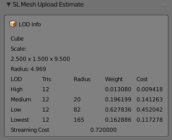
Using a Cube of the right dimensions we find the following information

A radius of almost 5m means that our HIGH LOD model will be visible to the default user setup within 20m. Now given that this is nearly 10m high and will sit on the side of a hotel, we can assume that many users will be seeing it from further than 20m away. So as we suspected the MED LOD needs to look good. What's more, the LOW LOD will kick in at 82m. Now this is New Babbage, visibility of 82m is unheard of but we can expect people to want a viable silhouette, so we'll have to make some effort on the LOW LOD too.

We know that my plugin values for the cost are over estimating but the proportions are probably not far off. Triangles in the MEDIUM are going to cost about 15 times that of the HIGH, with the LOW costing 3 times that of the MEDIUM

In fact, we can check this using an inworld analysis script.

Radius    Total LI  HIGH LOD   MED LOD    LOW LOD    LOWEST LOD
4.968652  0.729080  0.154618   0.348042   0.216630   0.009789
LOD sizes in tris :      197         30          6          1
LOD sizes in bytes:     3536        857        476        400
Cost per tri(LI)  : 0.000785   0.011773   0.037674   0.009767

We see that the ratio between LODs at that scale is:
HIGH/MED    15:1
MED/LOW      3:1

We can also see that our budget of 2LI is going to be tough.
SL rounds down so we can creep up to 2.5.
2.5LI is 3571 triangles in HIGH LOD.
For every triangle we put in the MEDIUM LOD we must sacrifice 15 in the HIGH
For every triangle in the LOW LOD we must sacrifice 45 in the HIGH

What is more, we are working on a symmetrical Mesh, every triangle we place on one wall becomes 4 in the final mesh so our full budget per wall is 892.

Making a start

I'd started with an octagon using 3 mirror modifiers to take a single face and reflect it up into 8. The idea would be to make the octagon then slice it in two. Very quickly I realised this was the wrong path (slicing a mesh in half is always best avoided) and instead switched to using array modifiers.

The model is built to be relatively efficient. All normal first stage optimisations have been made. The two most common for me are:-

  1. Remove hidden faces.
    This applies to any mesh creating workflow, when you work in Mesh Studio you do this before creating the Mesh by setting the face to be transparent. With Blender, a similar process can be applied. MY method is to create a "fake" material face could DELETEME, assigning any that faces that I find which cannot be seen as I go, deleting them later in the workflow.
  2. Remove duplicate vertices
    As you work you often end up with overlapping mesh and blender has a convenient function to remove duplicates. It has a slider to control the threshold (how near they must be) which is great for tidying up messy joints, but it needs to be applied with care or you'll lose small details by mistake. This is also a job that can take place numerous times in a workflow. For Example, if you apply modifiers, especially mirror or array modifiers, you may get duplicates left. 

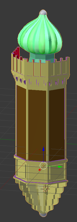
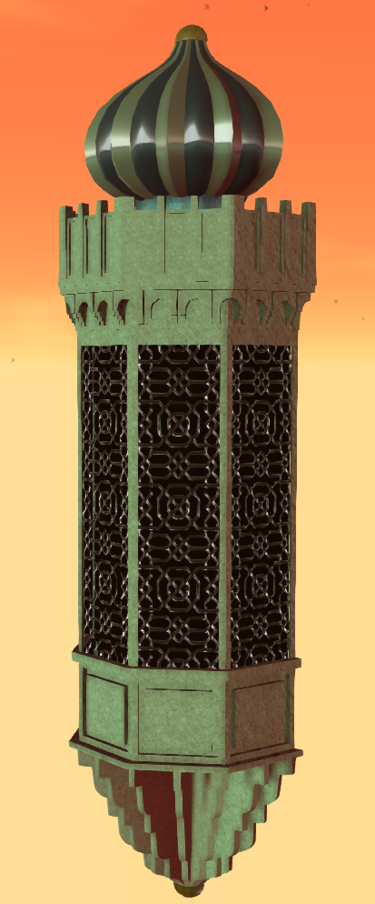
I modelled the main body, the crenellations, the dome and the lower corbel separately merging them into the joined model. The result was as follows:-


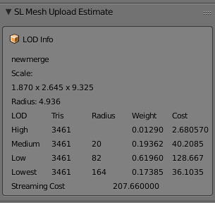
3461 Tris in my HIGH LOD Mode and coming in at around 3LI, now with the error in my AddOn we can suspect that this would be about 30% less. so perhaps 2LI, which will leave us nothing at all for the MED LOD. We are going to need to do some serious work to hit our target and frankly, I don't want to lose any of the detail I have if it can be helped.

Breaking it up - Bespoke optimisation

So what can we do? We've already done the basic stuff. We have a clean looking mesh, we removed all the doubles. So we now need to look at item specific tactics, is there anything about this object that we can use to our advantage?

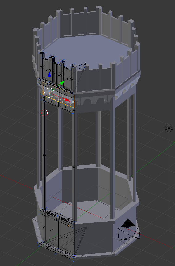
If we look at the object we notice a number of things. The main body is quite plain. I modelled the fretwork for the window but only used it to generate the textures and bump maps, apart from that it is really just a few inset panels. The crenellations are far more detailed with a curved and stepped arch. Then we have the dome, At first, I reused the old Aurora dome but quickly decided to recreate it from the start, either way, it has to have smooth curves and they are costly. At the bottom end we have the curved corbel another comparatively costly piece.

By linking all of these into one we are paying the price of a 5m radius object when by separating them out we van get those same triangles cheaper. Will it make a major saving?
Let's have a look.
LOD
HIGH tris
Radius
Cost
Notes
Combined
3461
4.94
2.680
All 4 parts joined and dupes removed
Dome
787
1.58
0.062

Crenellations
1650
1.77
0.164

Bay Window
276
2.82
0.069

Corbel
784
1.65
0.067

Separates Total
3497

0.362
Notice the slightly higher tri count.

So why would we ever join the mesh? The combined mesh has a couple of things in its favour.
Feature
Joined
Separate
Server Cost
Always 0.5
0.5 for each unit. In our case 0.5 x 4 gives us 2LI Inside out target so perfectly acceptable.
Texturing
Eight texture faces
Eight faces per unit. A lot more work perhaps. Also a lot more flexibility
Upload cost
Not really sure this matters
What's a few Lindens between friends?
LOD switch
A biggy. The LOD will switch based on the BB of the single unit
The LOD will switch independently for each item. This is good and bad. It can mean that the larger features stay as HIGH for longer than the small features. All the more reason to design good quality LOD models
LOD calculation
The crux of this issue. All triangles are going to be costed at the size of the overall object. Imagine a full-scale house with a mesh door knocker.
With the parts separated into sensible chunks we pay a more appropriate price and can choose where to place out details. This has worked incredibly well on our broken up window the High LOD coming in at about 13% of the merged

So what have we achieved, so far?

We had a hard target to hit at 2LI for a large and potentially fiddly mesh. My first "sketch" was coming in at 15LI with no other LODs and that seemed to suggest a big problem ahead. But by the time we've sanitised the Mesh to just what we needed and nothing more we were down to the low single digits. 

We then made use of the fact that this object has some large flat expanses that unhelpfully push up the scale. Breaking that down we have now reduced out HIGH LOD exposure to less that half an LI. Leaving us up to 2LI (remember LI gets rounded to the nearest whole so we can go to 2.5) for the remaining LODs. 

The bad news is that because we have broken this into smaller parts we now need to consider that the LOW LOD might be seen from nearer than before and a larger budget might be needed there.

Coming soon...

Next up we will look at the MED LOD model and see how we can keep our design goals and our LI budget aligned.


Friday, 19 August 2016

It's a material world

This post is another post in my Blender Addon series. We still have some distance to climb to get to the goal of LI estimation in Blender. The Chinese have an old proverb, often attributed to Confucious that states something to the effect "the man that moves the mountain starts by carrying away small stones." With a nod to Confucious, we will carry away an armful or two of rubble today and use those pebbles to make a useful tool that was on my wishlist, a "material usage report".

Materials matter

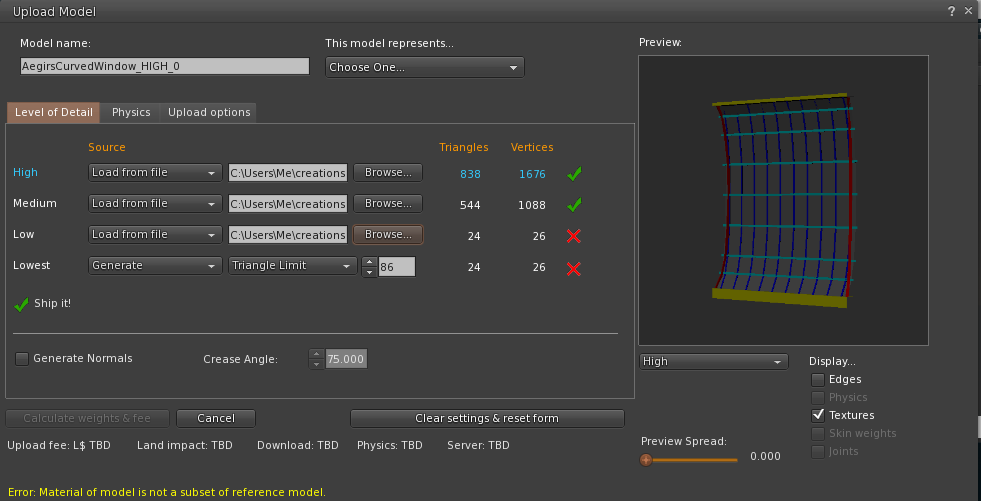
We know from a previous blog that the Mesh that we see is not how SL sees it, instead, it expects it decomposed into a mesh per material. It is in no small part this requirement that leads to the expectation that each LOD model will share the same material set. If you try to upload LOD models that have mismatched materials you will get an error such as this

The nasty yellow "Error: Material of model is not a subset of reference model" is the bane of a Second Life Modellers life, if you are anything like me, that is. Typically this occurs for one of two reasons; the first is that you've just messed up the materials, and you have a mismatch, that is easy to spot (it may or may not be easy to fix). The second reason is the one that, for me at least, is far more common. You've diligently optimised your model, removing all the internal faces that won;t ever be seen at a distance, simplified those pillars and struts and somewhere along the way you ended up with a material that is in the model but has no actual mesh associated with it. 

Looking in Blender will show the full list of materials that were used, you'll need to go through each in turn to find out which of them is actually empty. 

Gien that our grand tour will require us to cross this small hill on the way to the summit we may as well deal with it. We need to parse our object into materials before we can go much further, so let's count the polygons in each LOD as we go.

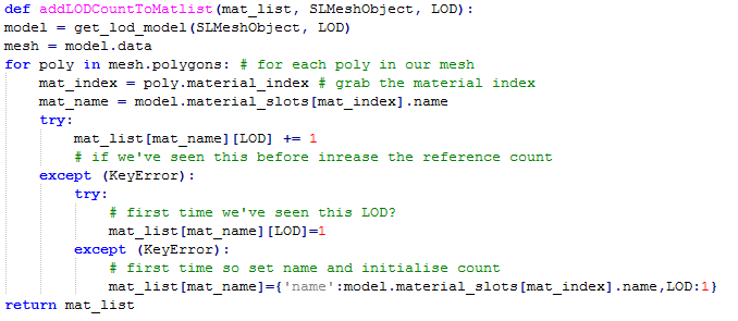
In Blender the mesh data has a list of polygons and each entry in this has a pointer to a material index the refers to the "material_slot" of the parent object. We can, therefore, write a short set of routines that will process the models that we have, building on the previous work that allows us to associate objects together as the LOD models and produce a composite report on the materials used by our LOD models and any errors that we find.


In my first stab at this, I used the material_index to build the map, and it worked perfectly because the model I was testing against had the correct material slots. When I tested with the object used to create the error above the report showed an issue, but it was not the right issue.

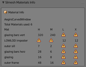
The curved window section above will be featured in another post, one on mesh optimisation and the lower LOD models are not complete because they (deliberately) do not have the same materials, but of course they do all have index 0. It is not the index that counts it is the material inside and given that the materials are kept per object, we need to use the name, not the index.

Having corrected that bug, we now find that we can reproduce the error from the SL uploader in Blender but provide more information to the user at the same time.
As you can see here, we are still able to show that the High and Medium LOD models are using the same subset of materials but that the LOW and LOWEST are not, what is more, the LOW and LOWEST are in fact using a completely disjoint set of materials, as evidenced by the warning sign in the high and medium LODs.

This is a contrived example to some extent, this is a work in progress and I knew it would not upload but hopefully you can see how the tool has saved a round trip of export and upload. 

Another example

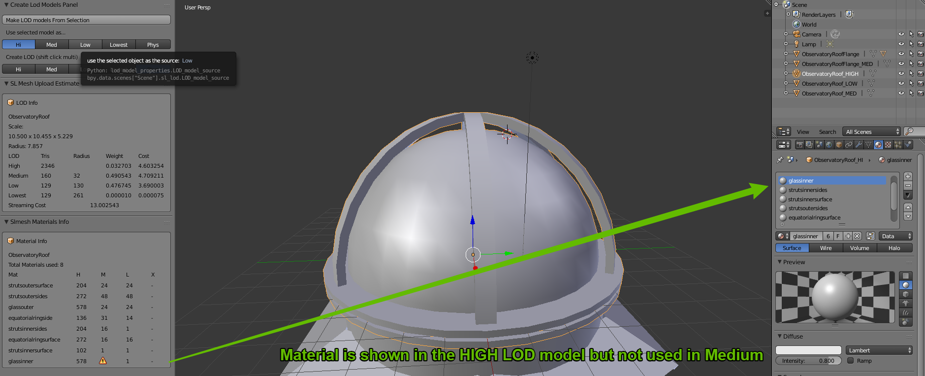
We have used a dome object I have built in the past in previous examples and so I will illustrate how the tool can quickly pin point a material issue and save time.

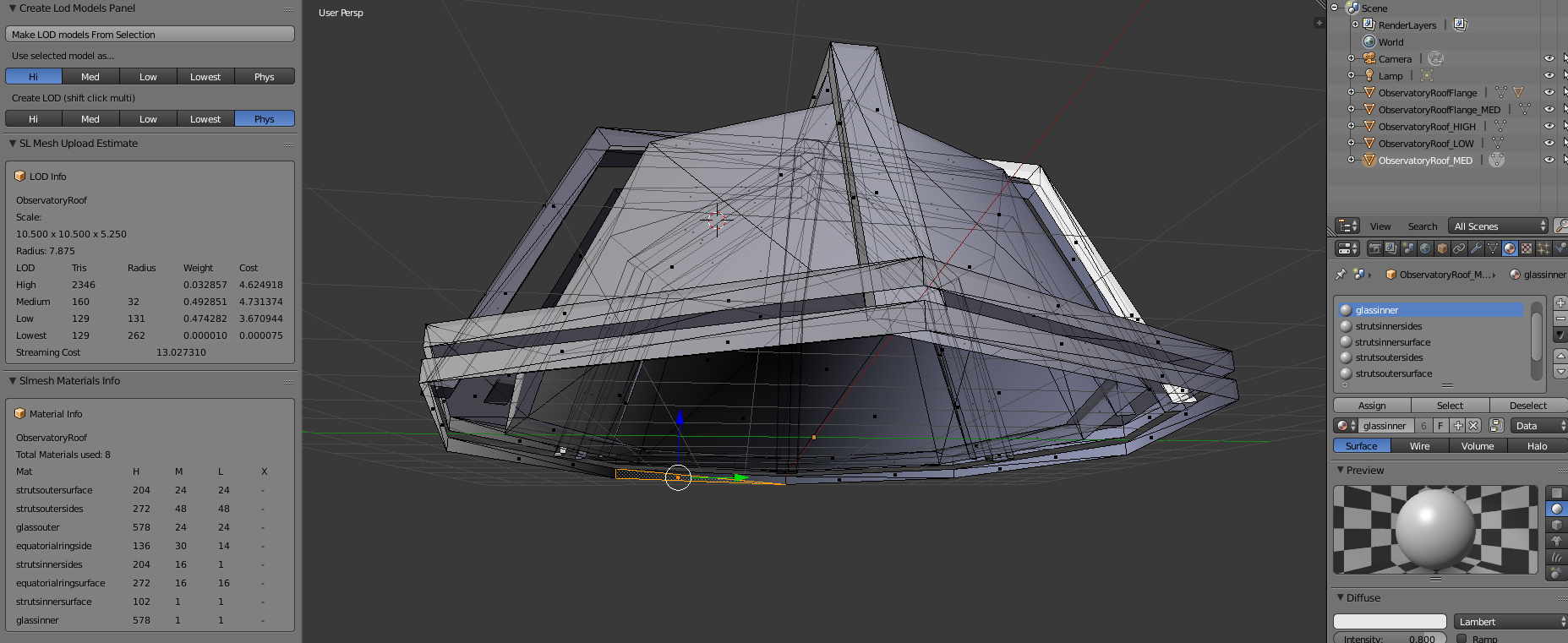
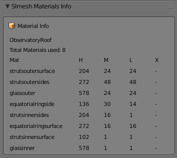
The first image shows the HIGH LOD model and the report is flagging up an issue with the "glassinner" material in the MEDIUM LOD.

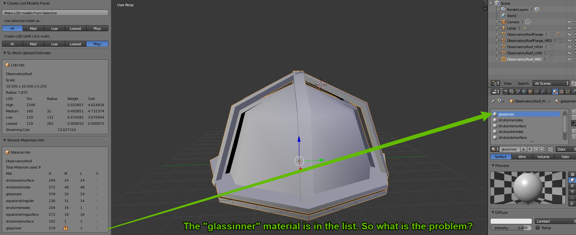
Now we see that the MEDIUM model has the slot in place, so it is not simply that the material is not there. We have to drop into edit mode to uncover the truth. While we were deleting all the interior mesh that would never be visible from in the MEDIUM LOD range, we accidentally deleted all of the  "glassinner" and so it is no longer matching the parent. So we can now assign a single triangle in the mesh to this material and it will fix the problem.


One last note, in the final report here on the left,  the LOWEST LOD (denoted as X due to the L for LOW) is marked as - and not an error.

This is because we have not defined a LOWEST LOD model in Blender and it therefore assumes that you will be generating this upon upload and it does not need to worry about it. Therefore, exporting the HIGH, MED and LOW objects and then importing them wil not give us any material based errors.
I think that these tools are now starting to offer value and if a few people are interested in becoming beta testers for me then I would love to hear from you. Contact me inworld or through Google+ from this blog.

As always, if you find this interesting or think it would be useful to someone please +1, share, whatever else. A typical blog entry here gets about 20 hits, I'd love to reach more people but only if what I am writing is useful.

Love
Beq
x


Saturday, 6 August 2016

Blender on the move - Travelling with Surface Pro 4 – update

Back in June, I blogged Travelling with SL noting some of the changes and early impressions of travelling with my surface pro 4.
At the time I mentioned the Blender also had some challenges due to the high-resolution screen and their default theme. I have since had a chance to take another look at Blender and found that there is a very simple change that makes it far easier to use.
The solution is a single simple preference change. The image below should tell you all you need but just in case, I will give a short step-wise guide beneath
blendersettings
Step by Step
  1. From the “File” menu select “user preferences…”
  2. On the user preferences dialogue, select the “System” tab
  3. On the left-hand side of the system tab, find “Virtual Pixel Mode.”
  4. Select “Double.”
  5. Finally “Save User Settings!
All UI elements should now be rescaled to something usable.
Have fun
Love
Beq
x
Monday, 1 August 2016

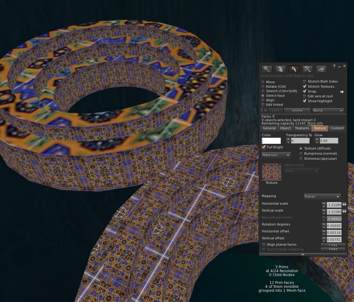
Mixing planar and non-planar faces in Mesh Studio

Something for the Mesh Studio afficionados today.

Mesh Studio has a "feature" insofar as it does not detect the mapping mode of a prim face. This results in an incorrect Mesh import later. First, a quick illustration of the issue and then how to fix it.

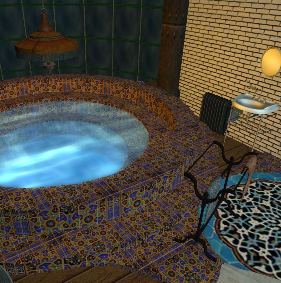
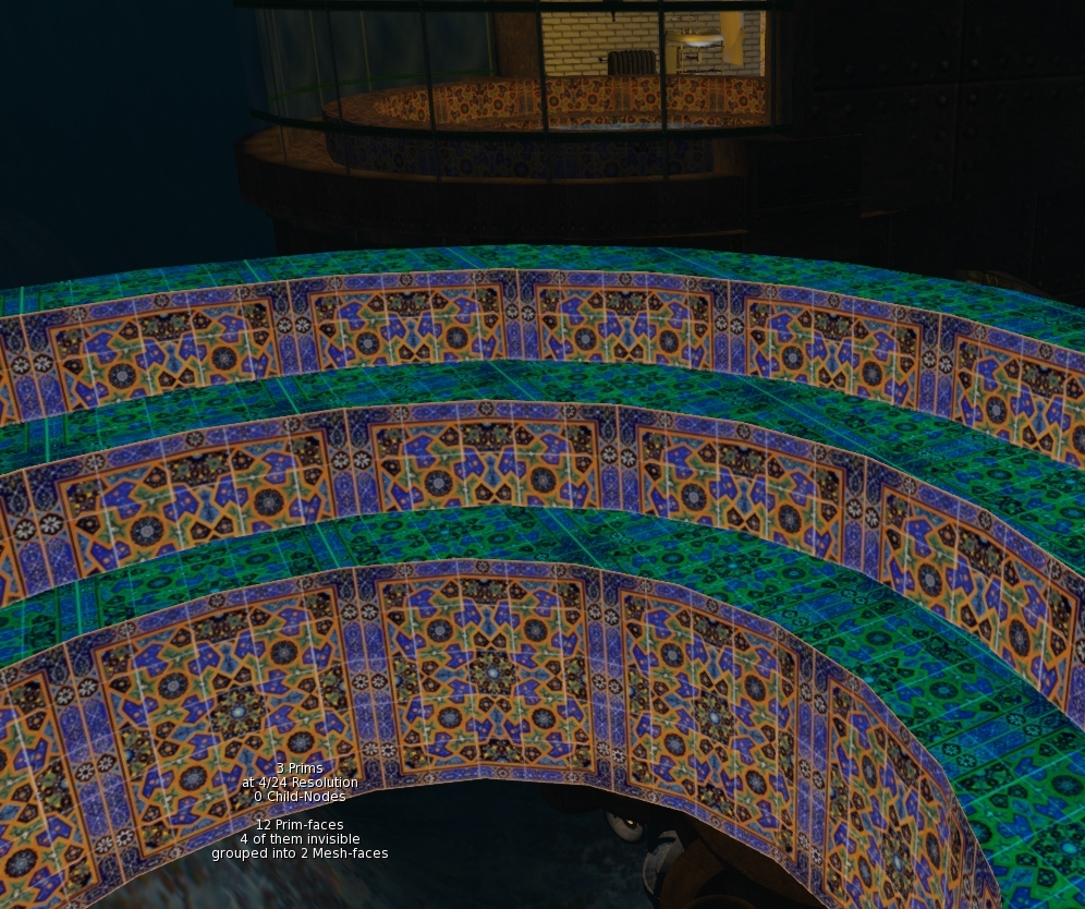
It is time to do a little more work on a slow burn project to gradually rebuild parts of my ancient underwater home. I've only got half an hour to spare so I want to Mesh the steps in the moonpool, so that I can safely apply some materials without it blowing up.


I quickly copy the existing object, tossed in the joined mesh script, eliminate a couple of the unnecessary surfaces and hit "Mesh".


A few moments later and I have it imported, apart from being a few Lindens poorer, we are good to go,aren't we? I drag the texture onto the Mesh and....ugh! That was a waste a Lindens, the texture UV mapping is wrong.

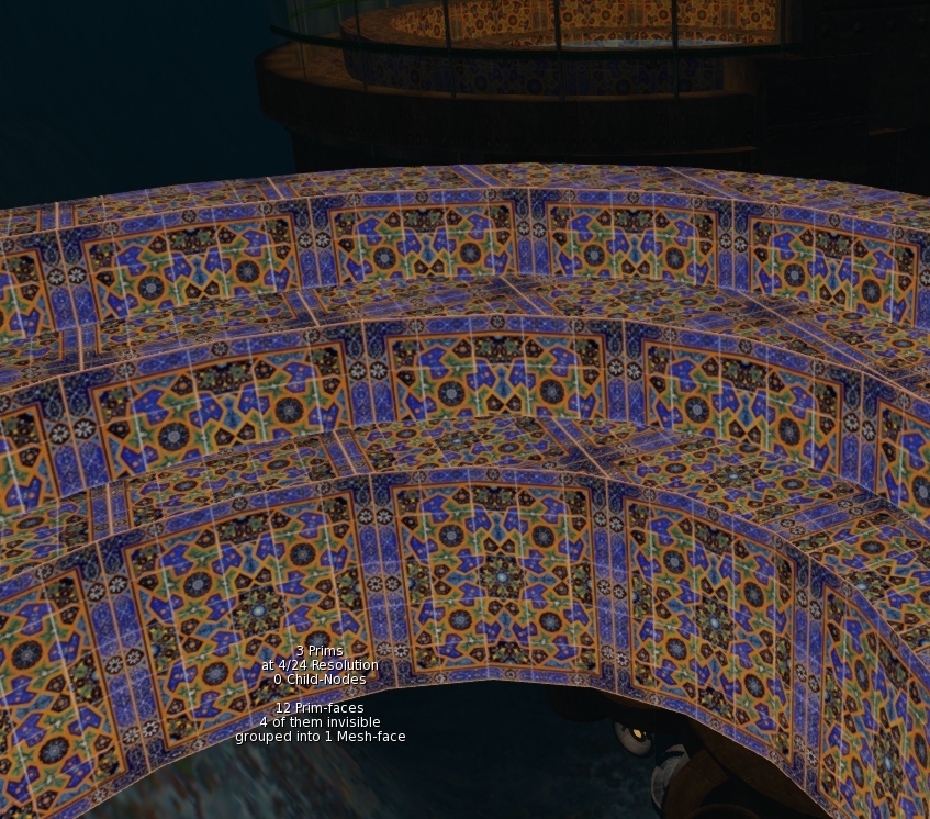
 A quick check of the source model and the reason is clear. While MS quite correctly noted that the texture UUID and the tint are the same on all the faces, it failed to note that top faces were planar mapped, while the inside cylinder faces were default mapped.


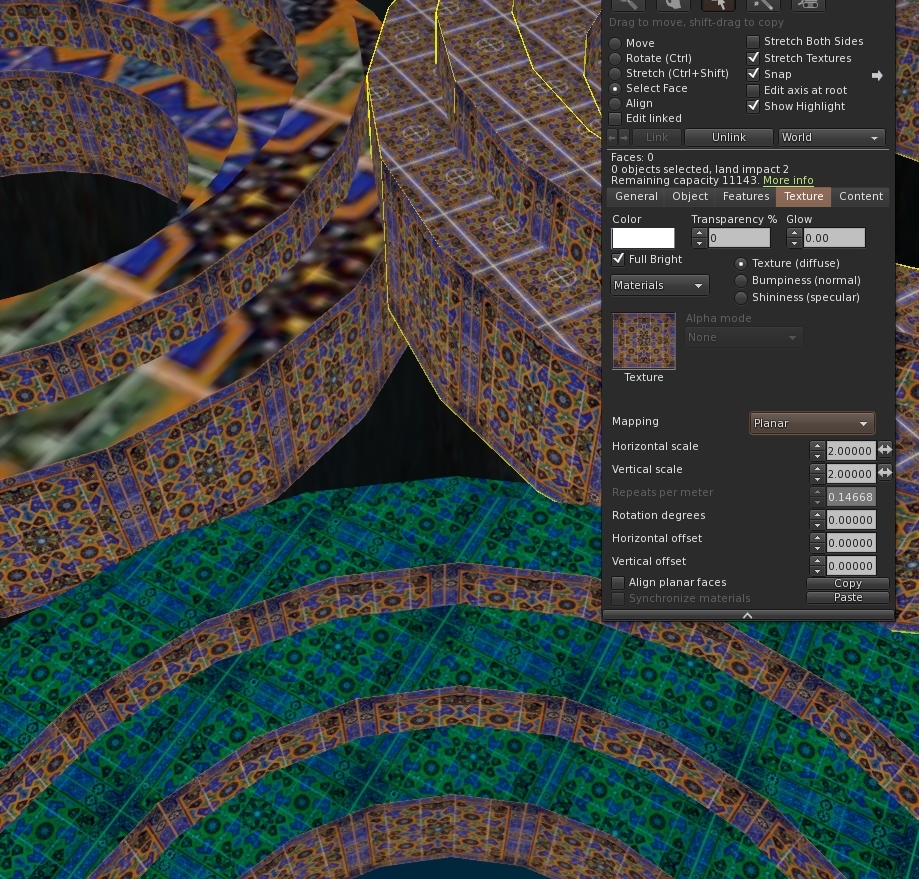
Happily, this is easily fixed. All we need to do is convince MS that this is a different face to the other one. We can do that by changing the tint value. A quick lick of paint and we find that MS now correctly sees this as having two mesh faces. and we are ready to splash another few lindens on an upload.


Rezzing the newly uploaded mesh we gleefully drop out texture on it and for a moment our hearts skip a beat. It still looks the same. Then we remember, it's called "default" mapping for a reason and sure enough highlighting the face and setting the mapping mode to planar snaps it back into shape.


And so there we have it. When mixing planar and non-planar with the same texture just make sure that they have a different tint.

If you have a larger build that will be painful to convert manually I have written a script that runs through the material list, identifies clashes and auto-magically changes the tint. Ping me an IM inworld and I'll send you a copy until I get around to putting it up to download somewhere.

I'm heading out for a couple of weeks so take care and more blogs when I return.
For now, I'll close with a quick recap of the steps with some materials applied to give the tiles that glazed shine.A bit overdone but mission accomplished for the Mesh at least.

Love

Beq
x


Saturday, 30 July 2016

Blender mesh data deep dive.

It's been a while since we last had a post on my quest to write better workflow tools for Second Life Mesh creators using Blender. In the last of that series, we took a long hard look at what exactly was meant by download cost and why our naive triangle counter was giving us such overestimates. Now it is time to try to use some of that knowledge to see how we can build that from Blender.

Decompression sickness

It was the compressed byte stream that was throwing out our numbers and, as a result, we will need to reproduce the data and compress it to find the byte streaming cost. This means that we need to look at how the polygons are stored in Blender.

We did a little of this when we were counting the triangles but we barely scratched the surface. 
All the data we need is in the bpy.data structure for a mesh object.

The BPY data structure is not very well documented but there is a lot of code around and the excellent blender python console that lets you try things out and features autocomplete.

Given an arbitrary mesh object (obj) we can access the mesh data itself through obj.data

import bpy

obj = bpy.context.scene.objects.active # active object

mesh = obj.data
Within obj.data we have access to a list of vertices and a list of polygons and a vast array of other attribute and views on the data.

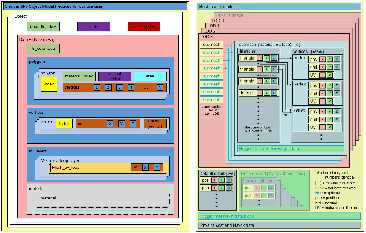
Following in the footsteps of the wonderful visualisation of the SL Mesh Asset Format by Drongle McMahon that we discussed in a previous blog I have had a stab at a comparable illustration that outlines the parts of the blender bpy data structure that we will need access for our purposes
On the left, we have my "good parts version" of the BPT datastructure, while on the right we have the SL Mesh Asset visualisation from Drongle McMahon's work.

We can now start to list out the differences and thus the transformations that we will need to apply
  1. SL Mesh holds all the LODs in one "object". We have multiple objects, one per LOD.
  2. A Mesh object has a list of polys that index into a list of vertices. SL has multiple meshes, split as one per material face
  3. SL only accepts triangle, we have Quads and NGons as well.
  4. Each submesh is self contained, with triangles, UVs, normals and vertices listed. Vertices are thus duplicated where they are common to multiple materials.
  5. SL data is compressed
So let's sketch out the minimum code we are going to need here.

For each Model in a LOD model set.
    Iterate through the polygons, and separating by material
    For each resulting material mesh
        for each poly in the mat mesh
             add new verts to the vert array for that mat. mesh
             adjust the poly into triangles where necessary
             add the resulting tris to the material tri array
             write the normal vector for the triangles
             write the corresponding UV data.
    compress the block

Having done the above we should be able to give a more accurate estimate.

A lot easier said than done...Time to get coding...I may be some time.

Love

Beq
x
    

Sunday, 24 July 2016

When is a door not a door? And other things they should have told you about physics

There are a couple of features of Mesh physics that come up time and again in group chat. They are the, "oh yeah, *that*, didn't you know about that?" type issue that makes building, or learning to build in SL an "adventure" at times.

The first one goes like this:

Eve: Help, I just returned my housemate's things.

Fred: Did you cut up all his shirts first?

Eve: no no, I was just sprucing up an old build on my platform and lots of things got returned.

Gloria: What do you mean "sprucing up"?

Eve: I have this, old hat I made years ago, I just modernised it by adding some bump and shine.

The second one, starts like this:

Andrew: OK, so I've done all the usual things and I cannot walk through my door.

Brian: Try opening it?

Cathy: set the physics type to prim

Andrew: Yes yes, done all that. It makes no difference. It's a bug in the uploader maybe? I have a wall, The physic shape looks fine in the preview.

This can run on until Andrew loses his cool... For now, though, we'll take a look at Eve's problem.

Physics accounting and the small thin triangles.

In the last blog entry of my Blender Addon Series,  we covered the Mesh asset format and looked briefly at the physics section. We learned from that that there are a few possible ways that a Mesh can convey its physical shape.

  1. A single convex hull. A mandatory shape for any mesh
  2. An additional decomposition of up to 256 hulls, each consisting of up to 256 vertices.
  3. A mesh designated for use by the physics engine.
More details of these can be examined on the Mesh Physics wiki page which has a lot of technical details that we will use in a future blog. For most people, if they specify a mesh model they use a low poly mesh and do not use the analyse button. This typically results in a lower physics cost but herein lies the problem.

Mesh physics shapes

By default when you provide a mesh shape for the physics, the viewer will encode this and upload it. Importantly, however, the physics resource cost is only estimated for the scale that you upload at. If you rescale it in-world it will change the physics cost. This may not surprise you, after all, the streaming cost increases as the size of an object increases, so why would the same not apply to physics? But, in what may seem an odd choice, the physics cost decreases with scale and gets larger as the object shrinks.

So why is this? It ultimately comes down to the cost of tracking objects.it is far more costly to track hundreds or thousands of tiny triangles that really don't add any perceivable value to the accuracy of the shape detection so in order to discourage such behaviour the Mesh accounting algorithm penalises mesh physics for the use of small thin triangles

Eve was only using prims, so why does she care?

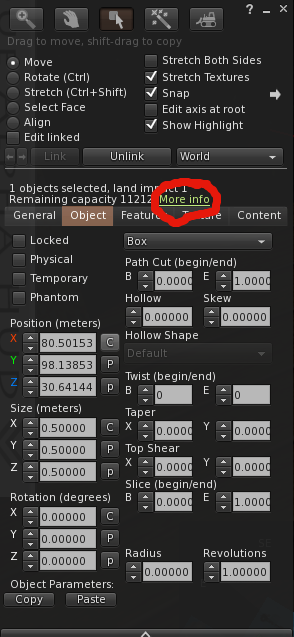
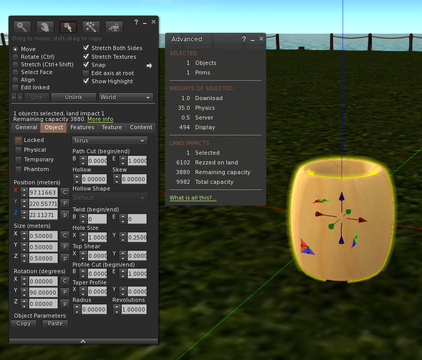
Prims have the dubious quality of being capped at 1LI when subjected to traditional accounting. This grossly under-represents their true cost in terms of rendering and lag but the internal physics cost is still calculated and you can see this using the "more info" button on the build/edit dialogue.


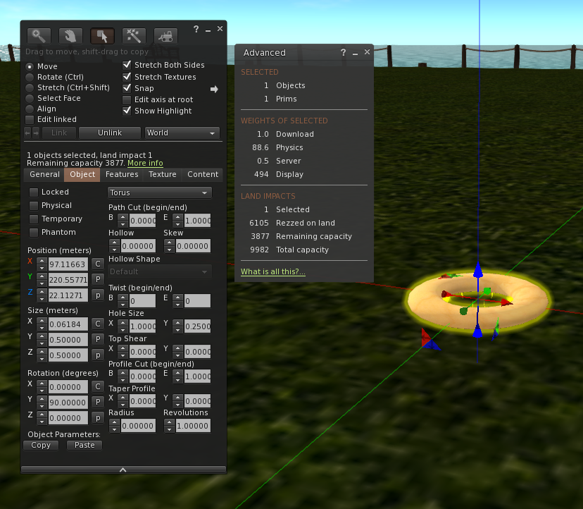
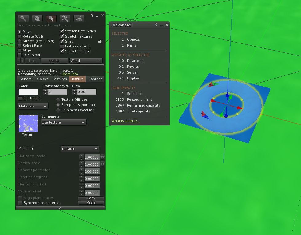
As you can see here the effective physics cost of the humble 0.5 0.5 0.5 torus is 35LI but due to the cap it is only showing as 1LI.

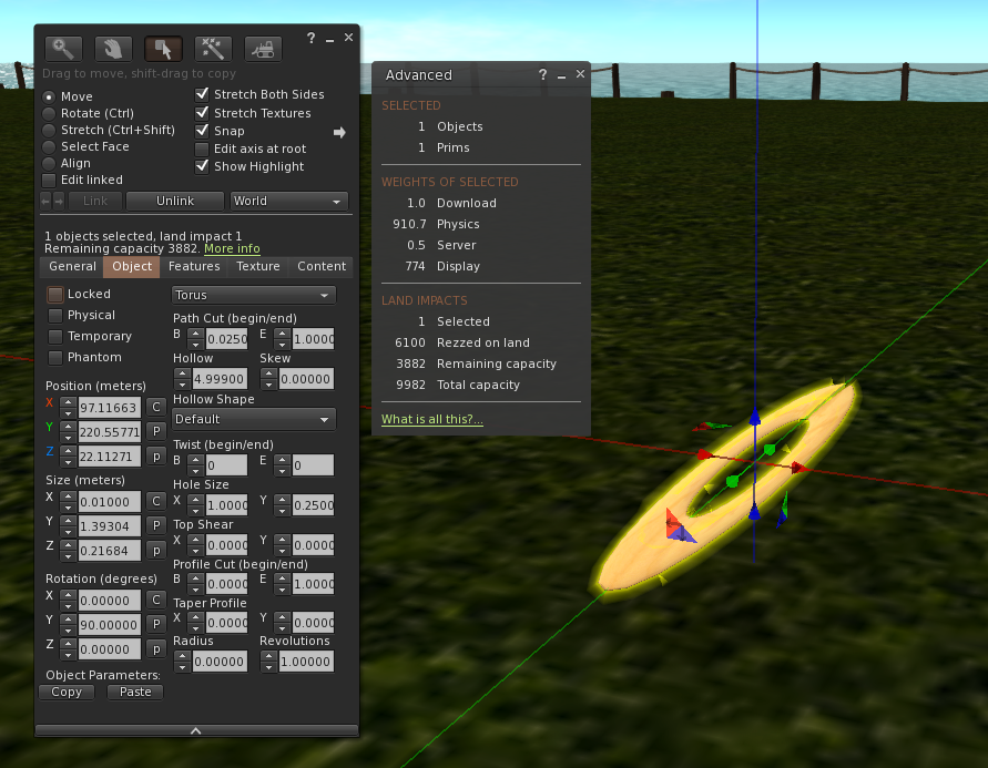
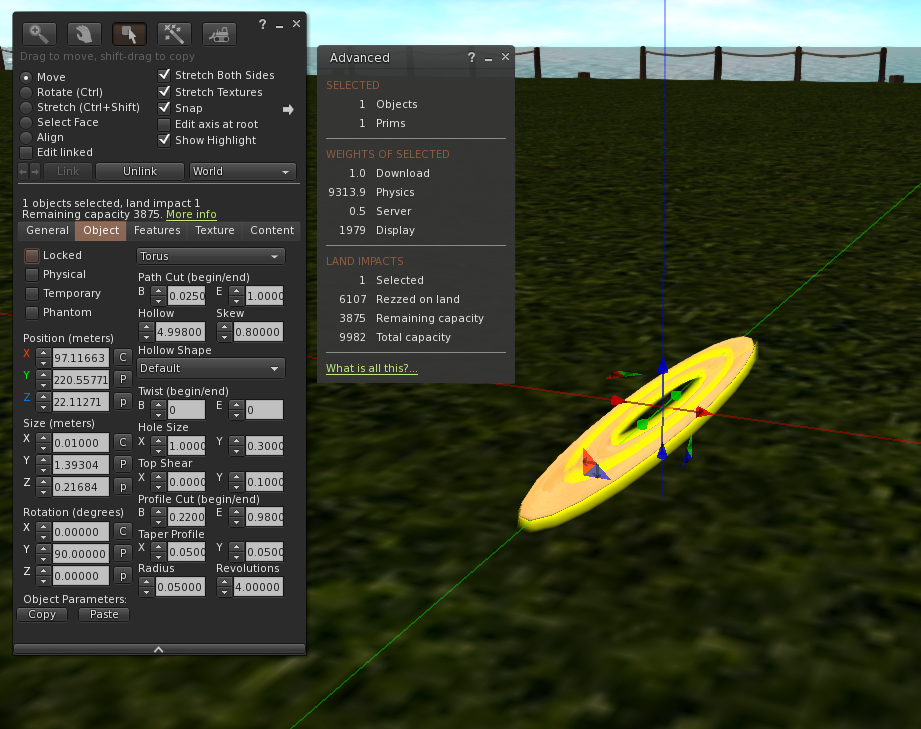
But it is not limited to 35LI. Because the physics cost is driven by scale and the "width of the triangles" compressing a shape massively provoke the physics cost.The next few images demonstrate the results of some minor torturing of a Torus.
By compressing it vertically we lift the Physics to 88.6

By making it long and thin we drive it up to a scary 910.7, but we aren't done yet
With some carefully applied torture incrementally path cutting, twisting etc. we can achieve a sim filling, sandbox burning, home destroying 9313.8 LI
Consider the above if you have legacy objects that consist of many tortured prims.
 If this were, however, only limited to the "hidden cost" this would hardly be a problem at all but it is not.

Unconstrained prims on the loose

When applying the cap to legacy prims, Linden Lab drew a line under what had gone before and protected it, thus avoiding breaking existing content. However, that rule does not apply to new features being applied to old content deliberately. 
There are two ways of breaking the cap. The first, perhaps most obvious way is to switch to modern "Mesh" accounting by changing the physics type to "convex hull". This can be done accidentally by linking a prim against a Mesh item. It can be pretty dramatic on a domed building or something with a lot of curved surfaces. 

All that glitters is not gold

The second way is more subtle and for the most part less well known and that is to apply a material to the prim. Materials were added a couple of years ago and provide for user defined bump (normal) and specular (shiny) maps. They are one of the quickest ways to modernise a drab looking older build, but they have a hidden surprise, as the moment that a material is applied to a prim it will switch to mesh accounting and reflect its "true" physics cost. 

It is this that Eve stumbled into in the mock scenario above. applying a spec map to an old prim necklace consisting of tortured prims is a great way to very quickly fill your parcel.

So take care when applying materials and linking legacy prims to modern items. You would not be the first person to find that a significant amount of damage has been caused.by an inadvertent ctrl-L

Damage limitation.

As mentioned above, the equation used to determine the physics cost divides by the width of a triangle. The mathematicians amongst you will already have realised that this means that the cost goes asymptotic as the width approaches 0. The 9000+LI that I managed to generate may not be the highest you can get (though it is the highest I have managed to drive a prim up to) but it is more than enough to do significant accidental harm accidentally. To limit the damage the viewer applies a simple constraint to save us. If the dimensions of the prim's bounding box go below 0.5 then the viewer will ignore the physics mesh provided and instead collapse to a simple solid convex hull. An example of this can be seen in the following image where our, previously 35LI, standard torus has been shrunk beneath the limit and now has a physics cost of just 0.1
.

and this brings as back to the question we started with...

When is a door not a door? When it's a hull.

and back to poor Andrew and his wall without a doorway.

Emily: Have you double checked the physics type?
Andrew: yes it's prim. I've done all the usual things, I've run out of options.

and so it goes on

Many times the cause of the issue will be resolved by asking one question.

Me: Andrew, What are the dimensions of the object?

Invariably, the response will be

Andrew: 20x4.5x0.1, I hate thick walls.

Inadvertently, by minimising the wall thickness Andrew has triggered the hull physics, blocking his door and ensuring it will never open. At this point ,Andrew has two options. He can either scale the x or y dimension to make the wall thicker (this is always the best test that this is the correct issue) or he can use the analyse function to produce a multiple hull based physics model that is not affected by scale and does not have the limiter applied. In general, the analysed physics costs more.

Summary

When you specify a mesh physics and don;'t analyse it, or when applying modern features to legacy builds, you open yourself up to physics issues. That can be summarised in a couple of rules
  1. Don't shrink any object with a physics shape without paying careful attention
  2. Don't apply a bump or spec map to a prim build without checking  for side effects.
It has a safety valve that can itself cause issues. Which can be summarised as:-

If your physics shape is set to prim, you are sure it looked right in preview (or metadata - see below). Check that no dimension <0.5.

Both sets of issues are resolved by using "analyse" but be aware that this frequently comes at a higher (fixed) physics cost.


A post script - One last tool in the physics armoury

If the scaling does not fix it then you'll need to prove whether the physics exists where it should.
One mistake that can be common with custom physics shapes is not ensuring that the BB matches that of the object. 
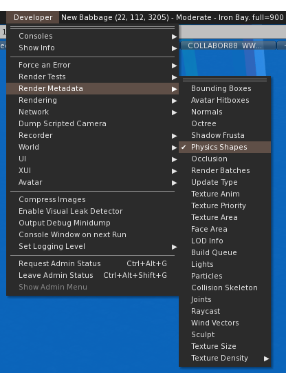
A tool that is specifically designed for tracking down physics issues can be found in the developer menu. (Note: the developer menu can be enabled from the viewer preferences.)
Go to the Developer->Render Metadata-> Physics shapes and tick it. The world will turn mostly blue.

The blue parts are physical surfaces, and, in fact, they are "heat mapped", an object with a very high physics cost will appear progressively orange and then red. More importantly, if you line the object you are inspecting, up against the skyline, you can see the areas that are not blue and which ought to correspond to holes/doors/windows. If the bounding box of the physics model does not match that of the LOD models then it will have been stretched/compressed to fit and any non-alignment will now be clear.

One word of caution when using this, however. There is a metadata display bug (at least that is what I consider it) that means that for Mesh objects, the mesh physics shape will be displayed even when the size restriction means that the default hull physics is being used. The convex hull shape can be seen when "convex hull" is explicitly selected, but will not show when it is being used because of the size limit. Interestingly this is the exact opposite of the behaviour I reported two years ago, so perhaps the change that addressed that problem fixed that and broke this?