Showing posts with label mesh studio. Show all posts

Friday, 8 June 2018

The Degeneration game - Nyrva's shower - a simple case study in physics shapes in Mesh Studio


I often come across frustrated builders who have struggled along the right path but for various reasons not quite got to the destination they had hoped. It often reads like a storybook, as our wannabe mesh warrior stumbles into the local inn, seeking solace and with a plea for help.
Nyrva: Hello, question please. If I am trying to build a "sci-fi shower" for RP, that you have to be able to walk inside of, do I have to make it square and boxy in the mesh and physics in order to avoid the "Degenerate Triangles" problem on import? It seems I'm not allowed to do a cylindrical design.


We meet our hero part way through their quest. They've already confronted the uploader troll, and unable to answer the riddle of the degenerate triangle, have retreated for help.


Back in the village tavern, our quester gets a lot of well-meaning advice. It variously consists or perpetuating myths and old wives tales, or valid advice that helped someone once, but does not really help our hero.
helpful soul#1: cylinders can be a pain ... i have found it "cheaper" to make the sides from a number of "box" type prims  for the physics
 helpful soul #2: your physics can be made up of a number of cube prims arrounged in a circle... sounds a pain ...but it is cheaper LI wise ( and i havent a clue why that is so ). I once made a smoke stack for a steam boat .... mesh funnel ... for some reason .... i forget why i need it physical ...... i was lazy and added a normal ( transparent ) cylinder when i added the prim cylinder to my mesh funnel the LI blew through the roof ....???? ( so i made a mesh physics one)
helpful soul #3: Also zeroing out the low and lowest LOD helps lower the LI because you wouldn't be looking at the shower from across the sim
In this case, all good advice in the right place and time but missing the point. Our embattled builder hacks away for a little longer, gets frustrated and gives up, limping defeated to the marketplace to buy something less fulfilling.

So what was the problem?

The MAV errors reported by the Second Life are often considered as dark arts, a kind of voodoo curse that nobody understands, but mostly they are just annoying badly reported errors. MAV comes from Mesh Asset Validation, so this was failing during the validation phase. OK, but what is a degenerate triangle? In mathematics, a degenerate triangle has zero area. In SL and other games use cases a degenerate triangle is one with a very small area. The degenerate triangle check, in SL, goes a step further and penalises "long thin triangles" which are defined as triangles where any one side is more than 10 times the length of any other side.

So the problem is that we have some tiny, probably stretched triangles. This is one of the reasons why I keep repeating over and over that a physics shape must be as simple as possible. If you have a triangle that fails the degenerate check you have definitely not optimised that model.

In the case of our intrepid mesher, they'd not removed all the hidden surfaces and thin edges. This is a common error, people think "this is a physics mesh, not a visible mesh so I don't need to hide the geometry, but it brings us back to rule #1 of physics shapes, every triangle that does not need to be there is a triangle too many.

Right then, how do I find these things?

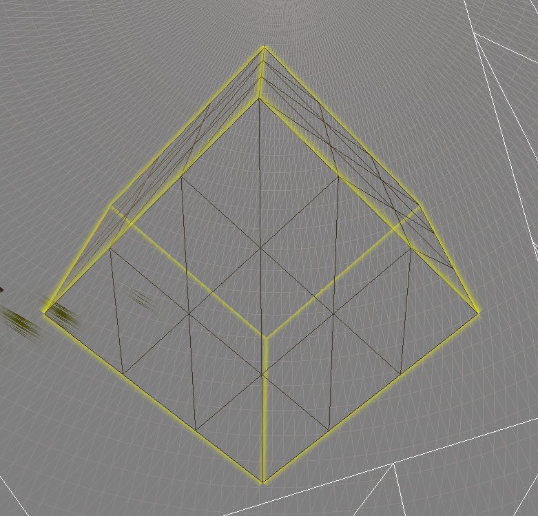
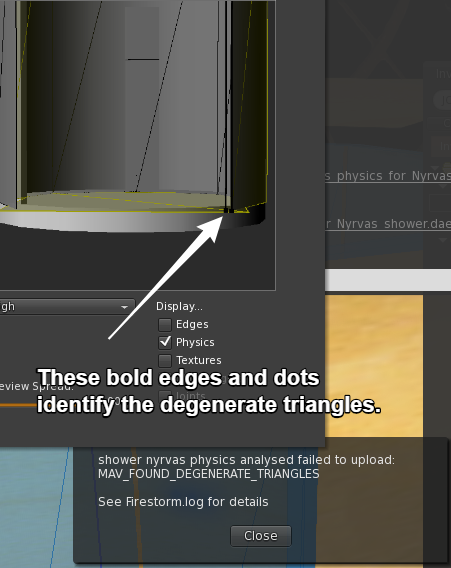
Once you know what the cause is, it is often quite obvious where the problem lies; however, what many people do not realise is that the much-maligned uploader tries to help you. When it finds a degenerate triangle it will highlight it in the preview window.

Happily ever after?

Does this story have a happy ending? We left our hapless builder being bombarded with advice over a beer in the local tavern, but how did it end?

Having been asleep when this tale started, I caught up with Nyrva when I woke to see how they'd got on. 

Me: Hi, did you get past your problem earlier?
Nyrva: no, never did. just wound up buying something off the MP for 55L$. I couldn't make anything below 5LI. For me, it's just another item on the "What MS can't be used for" list. lol!"
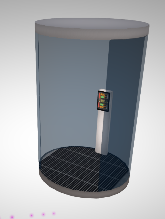

Never one to pass up a challenge I asked Nyrva to send me the item. I was able to get the shower to be 1LI with a full physics shape relatively easily. So what magic did I use? Nothing really just careful attention to that law of physics models, delete every triangle that is not absolutely necessary,

The rest of this blog is a brief step by step guide through the process.

The visible mesh is always a good starting point.
As we can see the structure is very simple, with no obvious reasons why we cannot get a very low LI. The only complexity is that it is cylindrical, in fact, the cubicle is just 3 cylinders, one of which is hollow and 1/4 cut. 

Cylinders are made up of a series of flat edges, a cylinder in SL is by default 24-sided, and in Mesh studio you can step down to as low as 3 sides (where your cylinder will appear as a triangular prism)
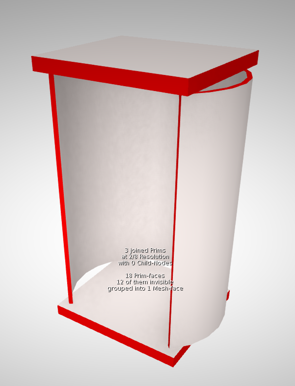

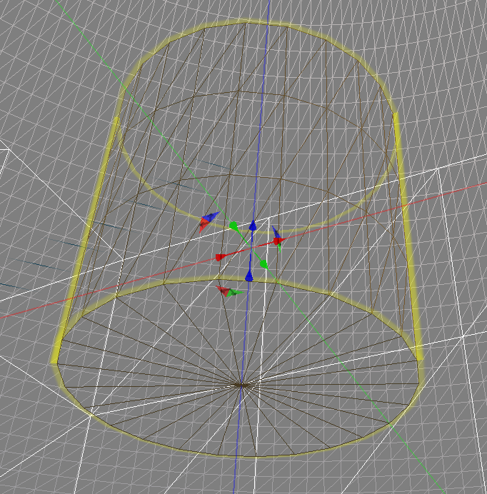
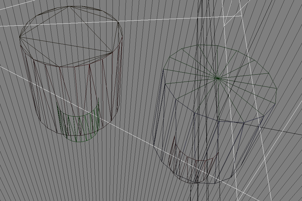
For the visible mesh in the High LOD model leaving the default setting will be fine. However, for the physics, we need to economise.  I chose to use the cylinder and set the number of side to 8 in Mesh Studio, with the quarter cut away this results in a 6 sided cut cylinder, which is 12 triangles on the inner face and 12 triangles on the outer. however, there are also two long thin triangles on the vertical edges and 12 small triangles on the top and bottom surfaces. These triangles are extraneous and also quite likely to be degenerate, I have marked them in RED to highlight them. All of these should be made transparent in the model before meshing.

The two "caps" top and bottom do not need to be curved at all. Leaving them as cylinders, even 8 sided cylinders would have resulted in 16 triangles ( 8 top, 8 bottom - assumes we remove the 16 around the sides). Unless there is a very specific need have the physics shape match the shower visual shape using a square and getting just 4 triangles is far more efficient.

Some of you will be shouting, "but you don't need the underside and the inside surfaces. It is true that the inner shower wall and the underside of the shower ceiling are probably superfluous and would have been the next optimisation if this had remained higher. Note that we cannot remove the underside surface of the floor because we need to have at least one triangle there to match the bounding box of the mesh and avoid stretching.

Uploading with the original visible mesh resulted in a 1LI cylindrical shower. 


Bonus feature

There was a curious outtake during the making of this blog. having duplicated the curved shower glass and used it as the basis of my physics, I made the long thin edges and the top surfaces transparent and generated a mesh.

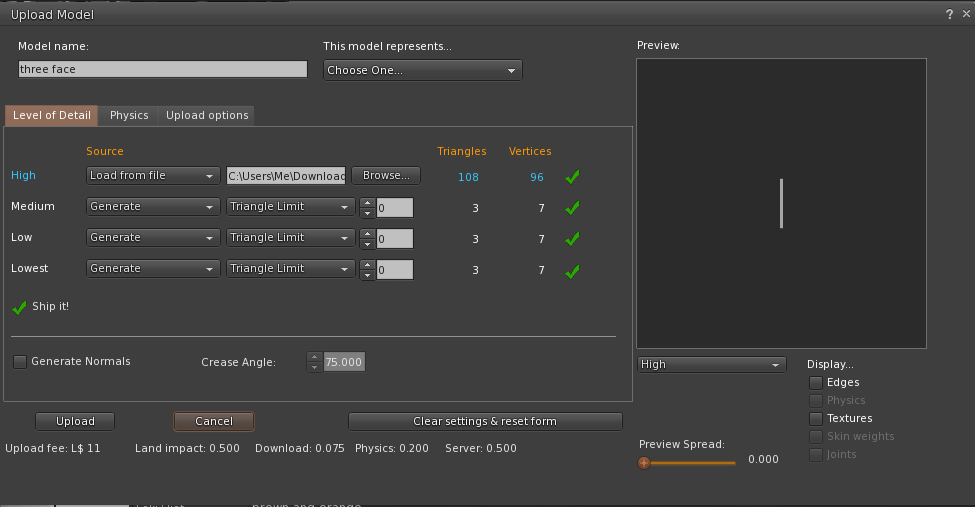
It refused to accept this as the physics, giving a Degenerate Triangle error. Looking at the image in the upload preview it was clear that the problem was that long thin cut edge, but it was equally obvious that there were no triangles there.

The problem was a little more subtle. Sometime during the editing of the original cylinder Nyrva had picked up a rounding error. and the cut was set to 1.2495 instead of 1.25. When Mesh Studio generates the mesh it obeys this. 0.125 is 1/8 of course. the size of one of our segments in our physics, so what Mesh studio was actually generating was 6 full-size sides and a tiny slither of the 7th side, which was of course, degenerate. Correcting the rounding error fixed the issue.

Saturday, 17 September 2016

How low can you go? An optimisation war story - Part 1 HIGH LOD tuning.

Einstürzende Neu "Babbage" bauten

A bad play on words to start a long blog :-)

When I walk around my beloved New Babbage I see far too many new Mesh buildings that collapse into a garbled mess as soon as I put my settings to anything close to that of a default user. Older buildings that are sculpted I can understand but with Mesh there is not really a good excuse.

So ask yourself, are you guilty of not paying attention to the "other" LOD models?

One of the drivers towards this is keeping low LI and an assumption that creating a proper LOD model away from the HIGH LI is both a lot of work and costly in terms of LI. In this short series, we will discuss a recent project and some of the strategies I used to meet a low LI target and ensure that the object remains visually consistent but more important a viable solid silhouette at a distance. It is not going to be an all answers guide to efficient building, and I am in no way the right person to write such a thing but hopefully you will see, through my recorded pain, how you might tackle a challenging build, achieve respectable LI and preserve credible LOD behaviour.

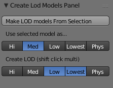
For an older guide to creating your own LOD models, especially those using Mesh Studio, might want to take a look at my 2012 blog Too much information - making your own LOD models

About LOD and how it is observed

As the above blog explains the LOD that will be displayed is governed by the radius of the object and the distance of the observer from it. But that is not the full story; there is a multiplier that can be applied that makes the LODs appear at a higher resolution for more of the time. This setting is known as the LOD Factor (aka RenderVolumeLODFactor).

Once upon a time, setting your RenderVolumeLODFactor as high as your viewer allowed was standard practice, you can still buy outfits whose associated readme tells you to do this to maximise your experience.

The LOD factor setting was used to combat the terrible construction of many sculpty based buildings. The fact of the matter, however, is that while users of Third Party Viewers such Firestorm can set this as high as 4, the Lab viewer is limited to a maximum of 2 and defaults to about 1.5 depending on your graphics capability. It is therefore, important to consider carefully your tradeoff between more detail in the HIGH LOD and better presentation in the lower LODs. In most cases, the MED LOD is the one that people will be seeing the majority of the time.

Managing Level Of Detail is still considered a dark art by many. I see far too many Mesh builders, both experienced and new that don't understand the factors that control when LOD changes or perhaps more worryingly choose to forget that most people in SL don't touch their Advanced Graphics settings. Building with low LI is easy if you don't care what it looks like to others, however, when building for architecture, anything that is going to be seen outdoors, in particular, careful attention to the LOD levels is very important to the overall quality of your build.

What should we be aiming for?

LOD
Primary goal
Bullet points
HIGH
Close up. Full detail. This is the only mandatory model.
  • Details
  • Clean Mesh
  • Strong basic outline with finer detail.
MED
This is arguably the most important Model. It will be seen by most of the people most of the time.
  • Same strong basic outline.
  • Flatten recesses
  • Remove interior faces and anything too thin to be seen from further away
LOW
This is only ever seen at a distance, it is important that the general silhouette maintains the volume of the build to stop the "crumple" effect
  • Maintain volume
  • Focus on the silhouette.
  • Flatten all detail focus on outline only
LOWEST / IMPOSTER
The last of all. This is very hard to deal with as a model and often the imposter solution is best.
  • Maintain silhouette where possible consider using spare material slots for imposters.

An arabesque challenge

I recently undertook a request from a friend who is busily rebuilding his property in New Babbage.
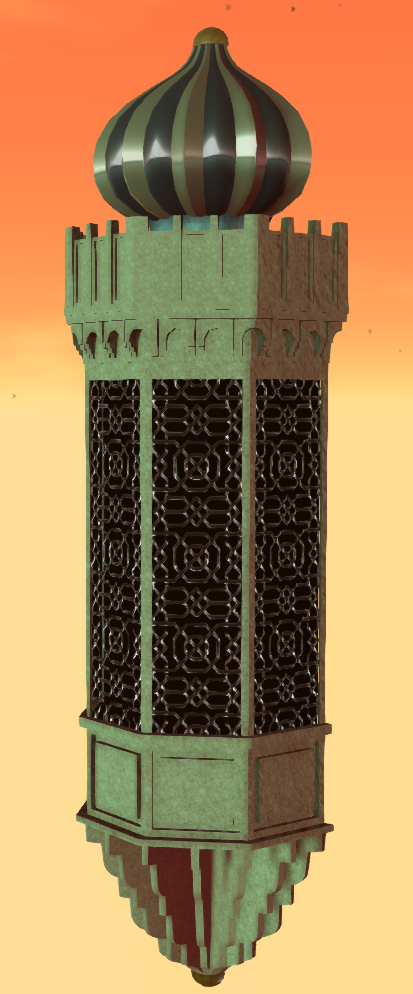
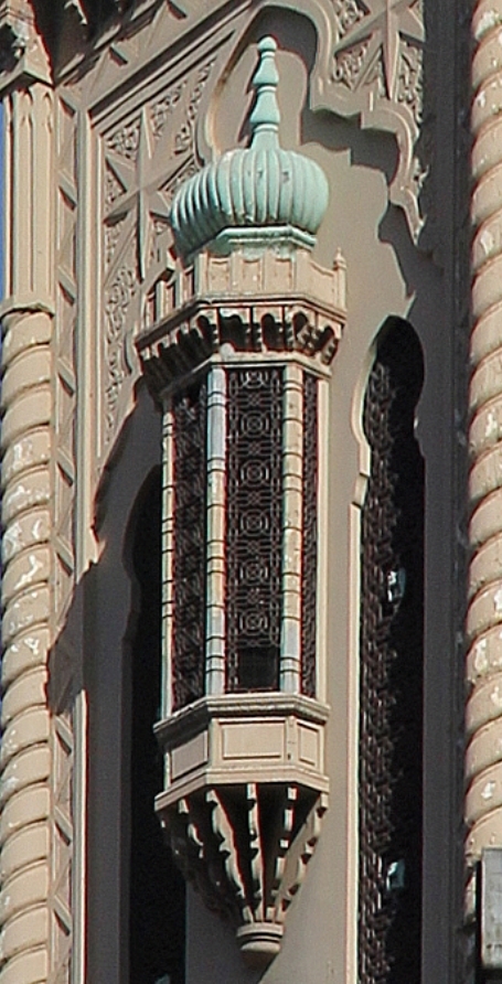
He desired an arabesque bay window, modelled after a theatre in Melbourne.

"No problem", I said. "what does it look like"

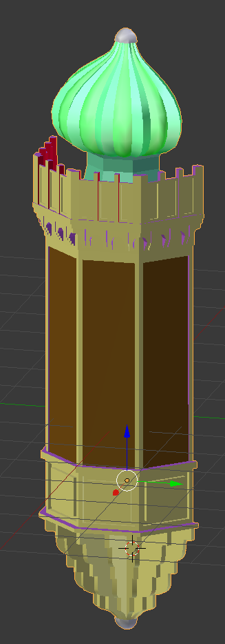
The photo shows the real life bay window. The onion dome on the top is reminiscent of the onion domes that I used in Aurora - my 2014 build for Fantasy Faire no doubt one reason why the job came my way.

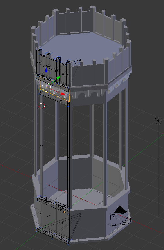
I often start a build in Mesh Studio but as I have been putting effort into my new workflow tools lately I decided to make this from scratch in Blender, so I set to work making an octagonal frame that I'd halve later.

I had of course forgotten two very important questions. "How big is it and how many LI do I have to play with?"

The answer came back the next day, it would need to be 9.5m high, 2m wide and about 1.5m deep,

"OK, that seems reasonable, what about the land impact budget..."

"About 2LI?"

Much teeth-sucking followed, 2LI for a large object with high detail was not an easy task.

"ookkkay." I said not wishing to give up without at least trying.

You may recall from previous blogs that the LI calculation is impacted by the scale, moreover, the issue is compounded by the realistic distance that an object will be seen from, and by whom.

If you are making a desk lamp, that will only ever be seen within your tiny office, and only ever seen by yourself, then you can take all manner of shortcuts that ignore the lower LODs and assume that the viewer has adjusted their viewer LOD multiplier etc.

In this case, though, we have a perfect storm of LOD and LI demands.
  1. Reasonably large in scale
  2. Visible from a distance as it is an external component.
  3. Seen by any visitors to the sim whose viewer settings cannot be "presumed"
  4. It needs to be low LI.
Large size means that the triangle rich HIGH LOD will be visible for a larger distance and this will put up the cost. The biggest cost is, however, going to be the MED LOD which will be visible across a very large part of the region, and thus is going to need to look pretty good.

Advice for the faint hearted

The following section *is* very long winded. It is about driving down the LI from an initial 15+ LI trial upload to the low target of just 2LI. I'll show you the working and comparisons but..

You don't need to do this to achieve results.
I find measurement is the best way to track your progress but that's just me. You can of course try these things on your objects and see how you get on without needing to measure every deatil.


Thinking about budget.

Let's do some quick maths then....no let's not, I wrote an AddOn for this...

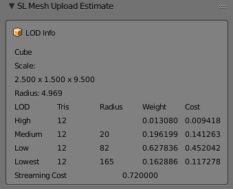
Using a Cube of the right dimensions we find the following information

A radius of almost 5m means that our HIGH LOD model will be visible to the default user setup within 20m. Now given that this is nearly 10m high and will sit on the side of a hotel, we can assume that many users will be seeing it from further than 20m away. So as we suspected the MED LOD needs to look good. What's more, the LOW LOD will kick in at 82m. Now this is New Babbage, visibility of 82m is unheard of but we can expect people to want a viable silhouette, so we'll have to make some effort on the LOW LOD too.

We know that my plugin values for the cost are over estimating but the proportions are probably not far off. Triangles in the MEDIUM are going to cost about 15 times that of the HIGH, with the LOW costing 3 times that of the MEDIUM

In fact, we can check this using an inworld analysis script.

Radius    Total LI  HIGH LOD   MED LOD    LOW LOD    LOWEST LOD
4.968652  0.729080  0.154618   0.348042   0.216630   0.009789
LOD sizes in tris :      197         30          6          1
LOD sizes in bytes:     3536        857        476        400
Cost per tri(LI)  : 0.000785   0.011773   0.037674   0.009767

We see that the ratio between LODs at that scale is:
HIGH/MED    15:1
MED/LOW      3:1

We can also see that our budget of 2LI is going to be tough.
SL rounds down so we can creep up to 2.5.
2.5LI is 3571 triangles in HIGH LOD.
For every triangle we put in the MEDIUM LOD we must sacrifice 15 in the HIGH
For every triangle in the LOW LOD we must sacrifice 45 in the HIGH

What is more, we are working on a symmetrical Mesh, every triangle we place on one wall becomes 4 in the final mesh so our full budget per wall is 892.

Making a start

I'd started with an octagon using 3 mirror modifiers to take a single face and reflect it up into 8. The idea would be to make the octagon then slice it in two. Very quickly I realised this was the wrong path (slicing a mesh in half is always best avoided) and instead switched to using array modifiers.

The model is built to be relatively efficient. All normal first stage optimisations have been made. The two most common for me are:-

  1. Remove hidden faces.
    This applies to any mesh creating workflow, when you work in Mesh Studio you do this before creating the Mesh by setting the face to be transparent. With Blender, a similar process can be applied. MY method is to create a "fake" material face could DELETEME, assigning any that faces that I find which cannot be seen as I go, deleting them later in the workflow.
  2. Remove duplicate vertices
    As you work you often end up with overlapping mesh and blender has a convenient function to remove duplicates. It has a slider to control the threshold (how near they must be) which is great for tidying up messy joints, but it needs to be applied with care or you'll lose small details by mistake. This is also a job that can take place numerous times in a workflow. For Example, if you apply modifiers, especially mirror or array modifiers, you may get duplicates left. 

I modelled the main body, the crenellations, the dome and the lower corbel separately merging them into the joined model. The result was as follows:-


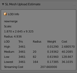
3461 Tris in my HIGH LOD Mode and coming in at around 3LI, now with the error in my AddOn we can suspect that this would be about 30% less. so perhaps 2LI, which will leave us nothing at all for the MED LOD. We are going to need to do some serious work to hit our target and frankly, I don't want to lose any of the detail I have if it can be helped.

Breaking it up - Bespoke optimisation

So what can we do? We've already done the basic stuff. We have a clean looking mesh, we removed all the doubles. So we now need to look at item specific tactics, is there anything about this object that we can use to our advantage?

If we look at the object we notice a number of things. The main body is quite plain. I modelled the fretwork for the window but only used it to generate the textures and bump maps, apart from that it is really just a few inset panels. The crenellations are far more detailed with a curved and stepped arch. Then we have the dome, At first, I reused the old Aurora dome but quickly decided to recreate it from the start, either way, it has to have smooth curves and they are costly. At the bottom end we have the curved corbel another comparatively costly piece.

By linking all of these into one we are paying the price of a 5m radius object when by separating them out we van get those same triangles cheaper. Will it make a major saving?
Let's have a look.
LOD
HIGH tris
Radius
Cost
Notes
Combined
3461
4.94
2.680
All 4 parts joined and dupes removed
Dome
787
1.58
0.062

Crenellations
1650
1.77
0.164

Bay Window
276
2.82
0.069

Corbel
784
1.65
0.067

Separates Total
3497

0.362
Notice the slightly higher tri count.

So why would we ever join the mesh? The combined mesh has a couple of things in its favour.
Feature
Joined
Separate
Server Cost
Always 0.5
0.5 for each unit. In our case 0.5 x 4 gives us 2LI Inside out target so perfectly acceptable.
Texturing
Eight texture faces
Eight faces per unit. A lot more work perhaps. Also a lot more flexibility
Upload cost
Not really sure this matters
What's a few Lindens between friends?
LOD switch
A biggy. The LOD will switch based on the BB of the single unit
The LOD will switch independently for each item. This is good and bad. It can mean that the larger features stay as HIGH for longer than the small features. All the more reason to design good quality LOD models
LOD calculation
The crux of this issue. All triangles are going to be costed at the size of the overall object. Imagine a full-scale house with a mesh door knocker.
With the parts separated into sensible chunks we pay a more appropriate price and can choose where to place out details. This has worked incredibly well on our broken up window the High LOD coming in at about 13% of the merged

So what have we achieved, so far?

We had a hard target to hit at 2LI for a large and potentially fiddly mesh. My first "sketch" was coming in at 15LI with no other LODs and that seemed to suggest a big problem ahead. But by the time we've sanitised the Mesh to just what we needed and nothing more we were down to the low single digits. 

We then made use of the fact that this object has some large flat expanses that unhelpfully push up the scale. Breaking that down we have now reduced out HIGH LOD exposure to less that half an LI. Leaving us up to 2LI (remember LI gets rounded to the nearest whole so we can go to 2.5) for the remaining LODs. 

The bad news is that because we have broken this into smaller parts we now need to consider that the LOW LOD might be seen from nearer than before and a larger budget might be needed there.

Coming soon...

Next up we will look at the MED LOD model and see how we can keep our design goals and our LI budget aligned.


Monday, 1 August 2016

Mixing planar and non-planar faces in Mesh Studio

Something for the Mesh Studio afficionados today.

Mesh Studio has a "feature" insofar as it does not detect the mapping mode of a prim face. This results in an incorrect Mesh import later. First, a quick illustration of the issue and then how to fix it.

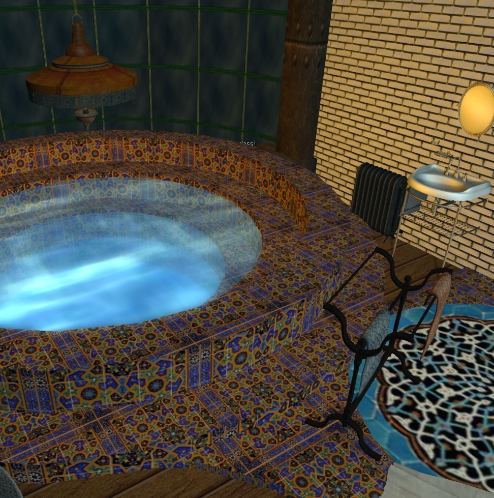
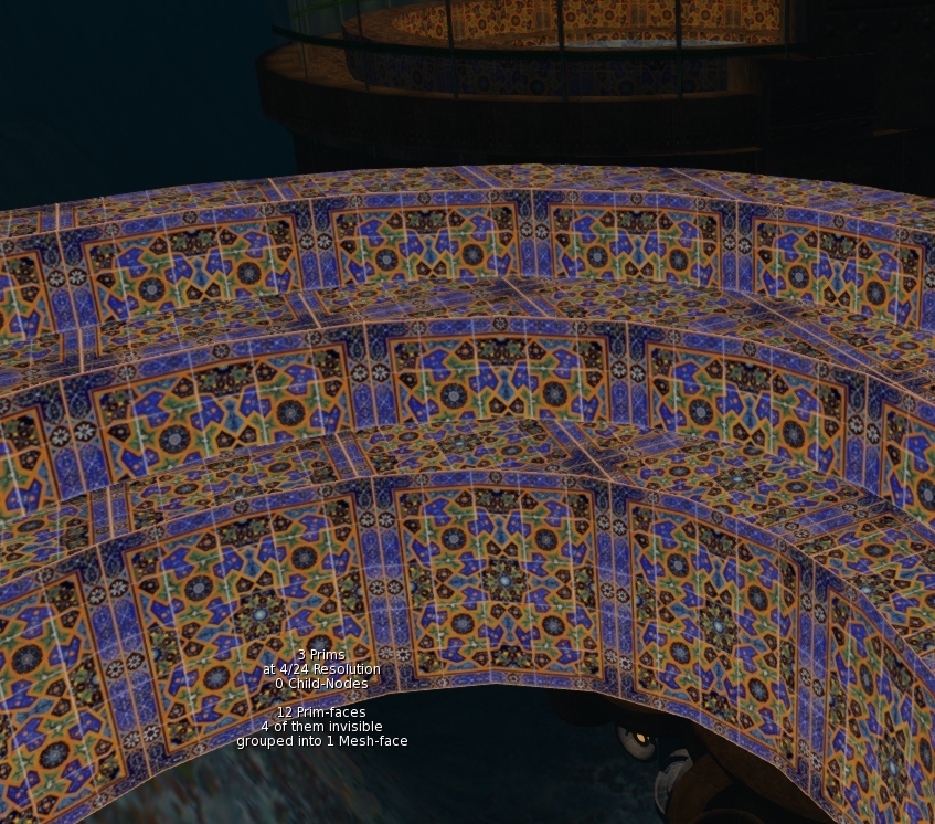
It is time to do a little more work on a slow burn project to gradually rebuild parts of my ancient underwater home. I've only got half an hour to spare so I want to Mesh the steps in the moonpool, so that I can safely apply some materials without it blowing up.


I quickly copy the existing object, tossed in the joined mesh script, eliminate a couple of the unnecessary surfaces and hit "Mesh".


A few moments later and I have it imported, apart from being a few Lindens poorer, we are good to go,aren't we? I drag the texture onto the Mesh and....ugh! That was a waste a Lindens, the texture UV mapping is wrong.

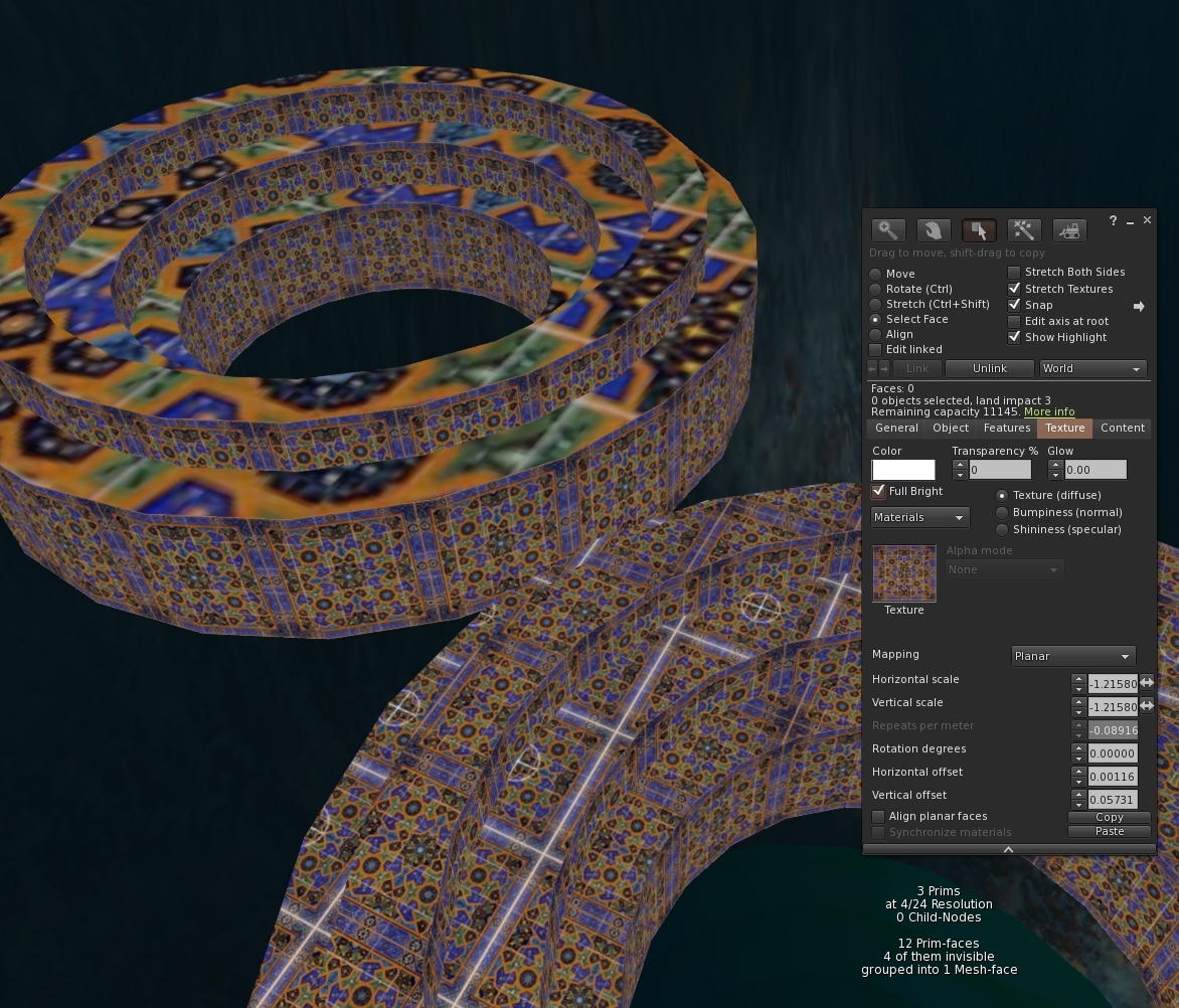
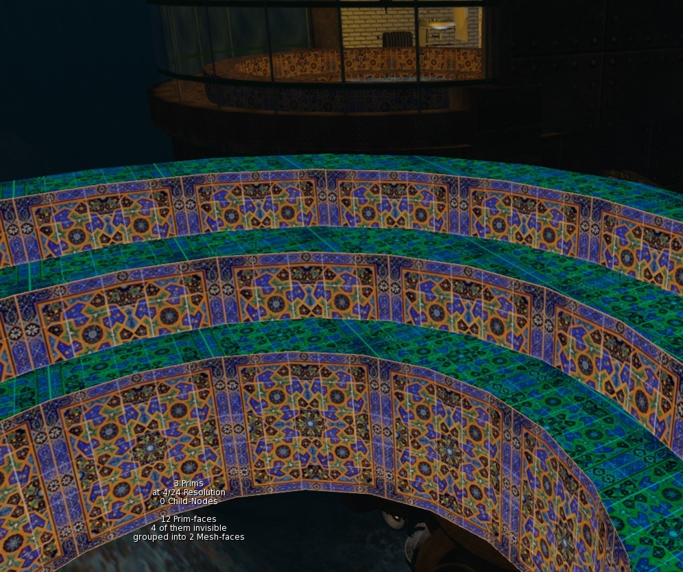
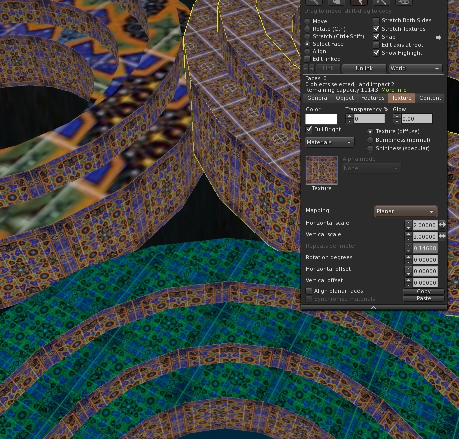
 A quick check of the source model and the reason is clear. While MS quite correctly noted that the texture UUID and the tint are the same on all the faces, it failed to note that top faces were planar mapped, while the inside cylinder faces were default mapped.


Happily, this is easily fixed. All we need to do is convince MS that this is a different face to the other one. We can do that by changing the tint value. A quick lick of paint and we find that MS now correctly sees this as having two mesh faces. and we are ready to splash another few lindens on an upload.


Rezzing the newly uploaded mesh we gleefully drop out texture on it and for a moment our hearts skip a beat. It still looks the same. Then we remember, it's called "default" mapping for a reason and sure enough highlighting the face and setting the mapping mode to planar snaps it back into shape.


And so there we have it. When mixing planar and non-planar with the same texture just make sure that they have a different tint.

If you have a larger build that will be painful to convert manually I have written a script that runs through the material list, identifies clashes and auto-magically changes the tint. Ping me an IM inworld and I'll send you a copy until I get around to putting it up to download somewhere.

I'm heading out for a couple of weeks so take care and more blogs when I return.
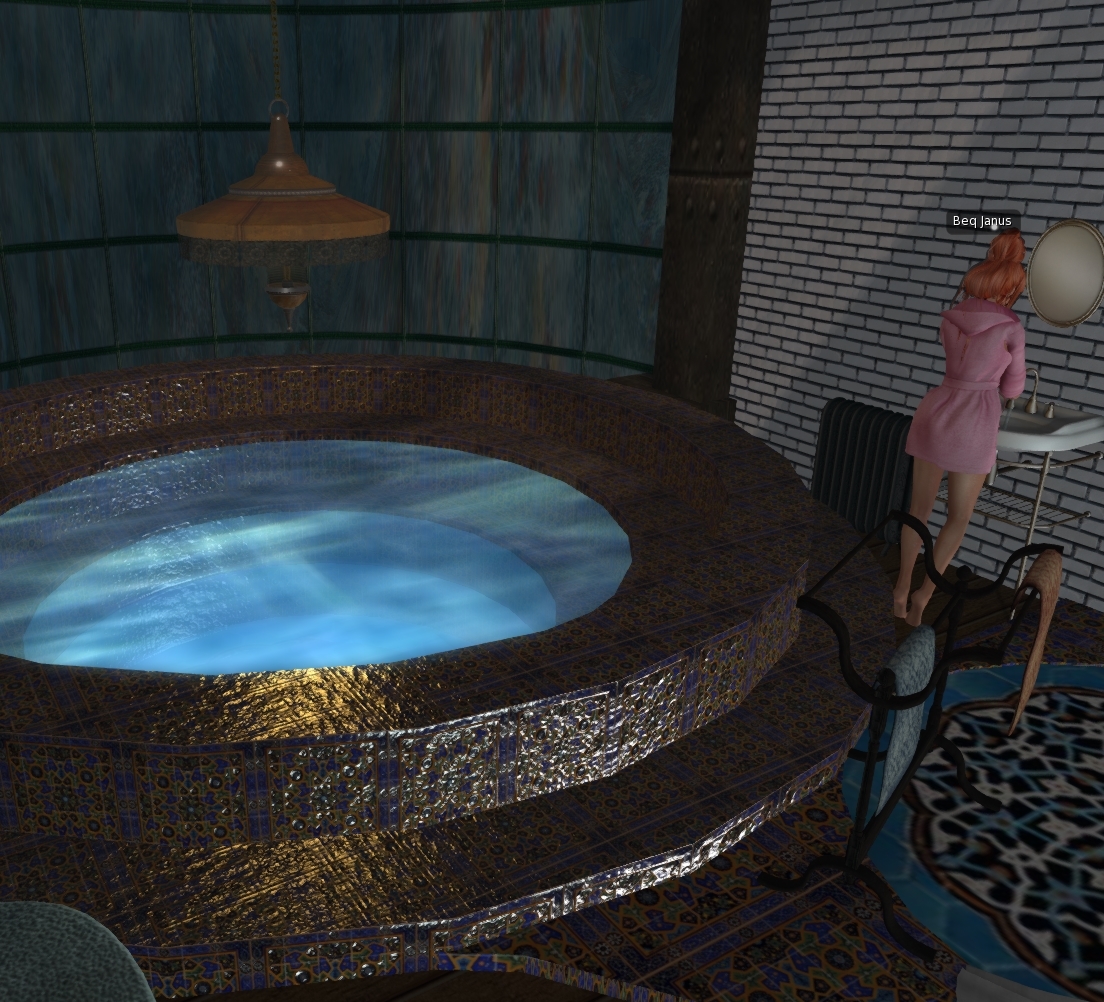
For now, I'll close with a quick recap of the steps with some materials applied to give the tiles that glazed shine.A bit overdone but mission accomplished for the Mesh at least.

Love

Beq
x


Friday, 22 July 2016

What did Mesh Studio ever do for me?

There have been a few reliability issues with the Mesh Studio servers of late and this has led to much grumbling from the beleaguered users.Mesh Studio is one of a number of inworld Mesh creation tools that allow you to generate Mesh directly from prims. Other tools, such as Mesh Generator, work in a similar fashion (with a similar price tag) but for me MS is that most flexible and easiest to use. But what exactly is it that MS does for us?

I've seen a few articles on the web about the mesh saving/export capability of Singularity, that was later adopted into Firestorm, often they will say things such as "I really don't see what Mesh Studio does that "save as" does not. This blog will demonstrate the key differences.

The problem with "save as"

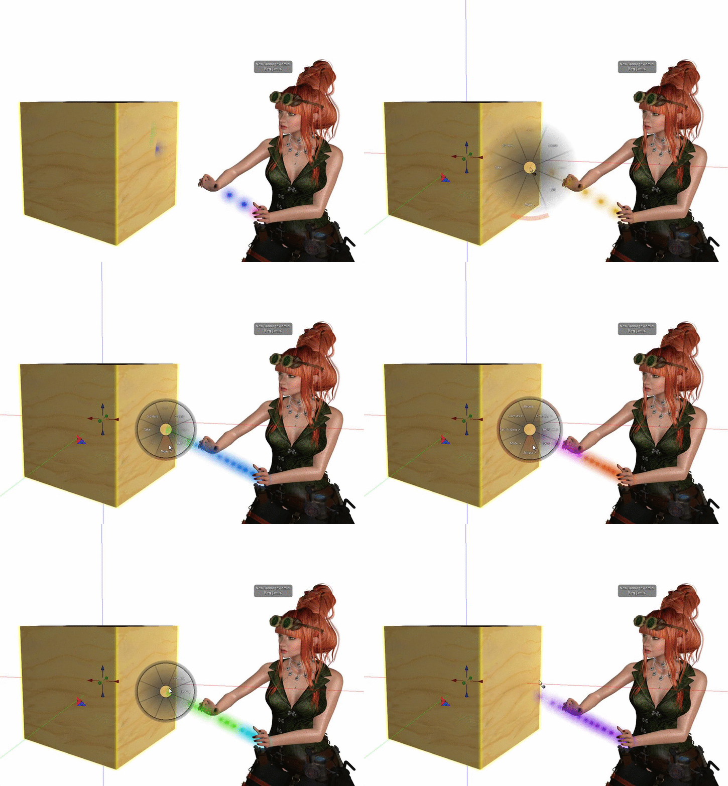
Save as can be found on the Pie menu in Firestorm (I can't comment on other viewers). The image below shows where it is. For Mesh, always pick "collada".

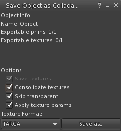
We can then "save as". The default options such as "skip transparent and "apply texture params" should be used.


We can then "save as". The default options such as "skip transparent and "apply texture params" should be used.

The "save as " function literally exports the mesh of the object, it does nothing more. The one exception being the very useful "skip transparent" which will not generate mesh for any faces that are set to be fully transparent. 

The result for a simple cube is a Mesh analogue of the following inworld image.
As you can see our cube is divided up somethig akin to a rubik's cube puzzle with each straight edge defined by 4 vertices. When theses vertices are triangulated it results in 18 triangles per side, or 108 triangles per prim cube. In most cases, splitting a straight edge makes no real sense. and results in extraneous vertices that add to the overall complexity of our object. Similarly all circles, be they parts of a cylinder or a sphere, are defined as 24 straight edges. By extension a quarter cylinder wedge has its curved edge defined by 6 straight lines.

In the image above we see a standard Second Life cylinder prim. The fan of triangles on the bottom shows us the 24 sides of the circular edge and then as we look along the straight sides of the cylinder we start to see the multiplying effect of that "4 vertices per straight" default. as our cylinder now has 24 slices, each consisting of two triangles, multiplied by three, plus another 24 triangles in each of the end caps, a total of 192 triangles. This is not a massive issue if you are using the model as HIGH LOD model and letting the importer generate the lower detail models for you. However, in a build of any reasonable complexity, if you want it to look good you will probably need to make at least a MEDIUM and probably a LOW LOD model. At this point you are going to pay a very high price for those ineffectual extra vertices.

The other, arguanly the largest limitation is that when exporting a linkset, every prim in the link set is exported as a separate mesh object, wrapped in a single .DAE file. Why is this an issue? It is probably exactly what you want it to do, if your objective is to export a prim build as-is but if you intention is to reimport as a mesh then the way that mesh uploads are accounted for has a word or two to say.

As we know, from other blogs I have posted, the mesh accounting has 3 components and the overall effective LI the larger of the three. For the most part we care about the streaming cost and the physics cost, the final member of this triad, the server resource cost is capped at 0.5 per mesh unit on upload (it can change inworld) . The key words in that previous statement are "per mesh unit", If you have a 32 PRim build that you are going to turn to Mesh, and you use "save as", if you do nothing else it will cost at least 16LI as each of those 32 units will be charged 0.5LI.

Mesh Studio to the rescue

Mesh Studio (MS) allows you the option to export things in many other ways. You can control the number vertices in a straight or circular edge, you can ask it to weld all the prims in a linkset into a single mesh object. It supports the "skip transparency" option that we saw in the "save as" but extends this to allow 

We can now use our model to generate the Mesh that we want at a complexity that is sensible. In general I never use 4 for straights, I have not found any good reason for it yet. The curve setting is very useful allowing your to make smoother curves that SL default for your high LOD model and then drop to a coarser 16 and even 8 sided curve for low LOD levels. 

To get an idea of how I tend to work with Mesh Studio, you can watch my timelapse clock building video found on my Vimeo page.

"But Mesh Studio servers are down and I really need to get this Mesh finished."

The downside of the in world mesh creation tools is that they depend upon external scripts to perform the mesh conversion if for some reason they are not available then the Mesh creation process will fail. 

I hear a lot of people complaining about this when it happens, about how their business depends on it etc. and frankly I don;t have an awful lot of sympathy for that position. If you have a business that is important enough in terms of revenue that a day or a week of delayed production is critical then you need to have a backup plan. 

You have two real options. The first is to use another inworld service and hope that they are not both impacted at the same time. One slight drawback here is that (as far as I have been able to tell) the functionality of MS is not fully available in any other product, the nearest is Mesh Generator but it does not support a number of advanced MS features such as linked sets or more crucially, arbitrary definition of the complexity (that ability to set any value for the number of circle segments), Mesh Generator in this case does allow changing it but only to pre-defined values.
If anyone is able to correct my understanding here please contact me inworld, as my experience is only through the limited documentation and the demo version.

The second option is to use an off world tool. Choice of these tends to come down to personal experience and in some cases biases but it is also largely about budget. Maya uses swear by the power of their tool, but unless you have access to a student version it is going to cost you of the order of 2000 USD (possibly per annum?). At the other end of the spectrum is the phenomenally powerful, but ever so slightly (very) scary, Blender. 

A lot of people find Blender to be impenetrable, and it can be daunting especially if you are used to the very simple and friendly in world tools. However I would suggest that a few very simple commands that most people can manage to memorise will allow you to get close to the same quality of Mesh that Mesh Studio will output, starting from a "save as" output.

To demonstrate this I recently made a very quick and dirty video.

The video shows me importing a 110(ish) prim model that I had hoped to generate am MS output from. I guide us through joining all the objects together (bringing the LI down from 55 to 7) and then cleaning up all those extraneous vertices.

So does that mean I don't need Mesh Studio now?

What I hope it has shown you is that Mesh Studio saves you a reasonable amount of fiddling around. It may only have taken a few minutes but consider that you need to do that for every iteration if your source model remains the inworld version. Every time you change the model you will need to clean it up. But there is another issue, that of UV mapping. 

Both MS and "save as" do a pretty good job of exporting the UV mapping of the textures, What is less clear is whether that editing survives the clean up process.I most cases I tend to remap the UVs so it is not an issue for me, however I did conduct a test and both the Mesh Studio model and the Firestorm Save As model survived the cleanup commands as shown in the video.
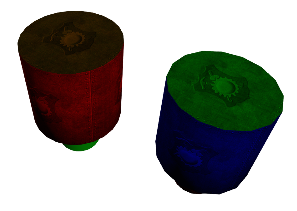
The image above shows the MS export on the right (exported at 16 sides per circle) with the FS save as export on the left. Both were cleaned up using the same method, however, the MS mesh did not have a limited dissolve applied. The net effect of this is that it retained the triangular fan on the cylinder top while the FS export has a rather uglier geometry.

In summary

By using Mesh Studio you automate a number of mesh optimisations that you might otherwise have to do when operating on a round trip workflow from Prim to Mesh. By performing these operations reliably and repeatably in world it makes the process more efficient and of course, for many simple items allows an immediate reimport of the Mesh at a considerable LI saving.

I hope this helps some of you to have a look at how Blender or similar tools can help you out in a fix, but also serves to remind you that the 20 dollars spent on MS was a pretty good investment.

Love 

Beq
x

Tuesday, 5 July 2016

Snake charming in Blender part 3 -

This blog post is the third in the series of posts on my Blender AddOn adventures.

Previously:-
Post 1 - We started to put a simple addon together to generate five copies of a selected Mesh and rename them according to their intended use.
Post 2 - We took it a step further by allowing the user to select which LOD to use as the source and which targets to produce.

At the end of the last post we had the user interface elements working but they had not be wired up to the addon itself.

The code for this blog has taken a while for me to get to the point where I am properly happy with it as it required a bit more background reading to make the work covered in the last blog initialise itself correctly. This blog post, however, should be quite short and then we will move on to something more interesting.

In the first, naive, version we had a simple function that created 5 duplicate copies of a base object. There are lots of different workflows that can be followed and, for me at least, it varies a little depending on what I am building, where I am starting from etc.  I work on a Mesh I often end up working in two directions. I upload a template made using Mesh Studio in SL, this gives me a proforma with the right scale and a little confidence that it will fit where it needs to. That template can often evolve into the medium LOD, then get duplicated, adding detail and refinement to use as the high LOD model and then removing things from another copy to form the low LOD.

It was also a good chance to refactor the repetitive code from the first version.

The execute method of the operator is now far more generic. I have created support functions for stripping the LOD extension from an object name. This means that I can quickly get from any LOD model to any other by removing the extension and adding another, the upshot of this is that you do not need to be looking at the HIGH LOD model in order to generate another clone from it.

def execute(self, context):
# For every selected object
        for object in context.selected_objects:        
            basename = self.getSLBaseName(object.name)  
# strip the _LOD if any to find the "root" name
            source = self.findOrCreateSourceModel(basename, context)
# locate the source LOD Model if it exists, if not create it using the selected mesh
            if(source is not None):
                for i in context.scene.sl_lod.LOD_model_target:
                    # For every target LOD clone the src and relocate it to the correct layer
                    targetModel=self.createNewLODModel(source, self.getLODAsString(i))
                    self.moveToLayers(targetModel, {int(i)})                    
        return {"FINISHED"}

That's all for this blog, it was wrapping up a few loose ends, though the brevity of the blog does not reflect the pain of learning how to get properties to register properly in Blender.


Saturday, 2 July 2016

Tell your friends - An old bug that people really ought to know about.

I was reminded today that people remain largely unaware of an old bug spotted five years back by Drongle McMahon and which remains unfixed.

I first became fully aware of this during an investigation with Antony Fairport and the ensuing discussions with Rey (Chinrey). Given that it remains a problem and that many people do not realise it, I thought I would write a quick and concise (by my standards) example of what the problem is.

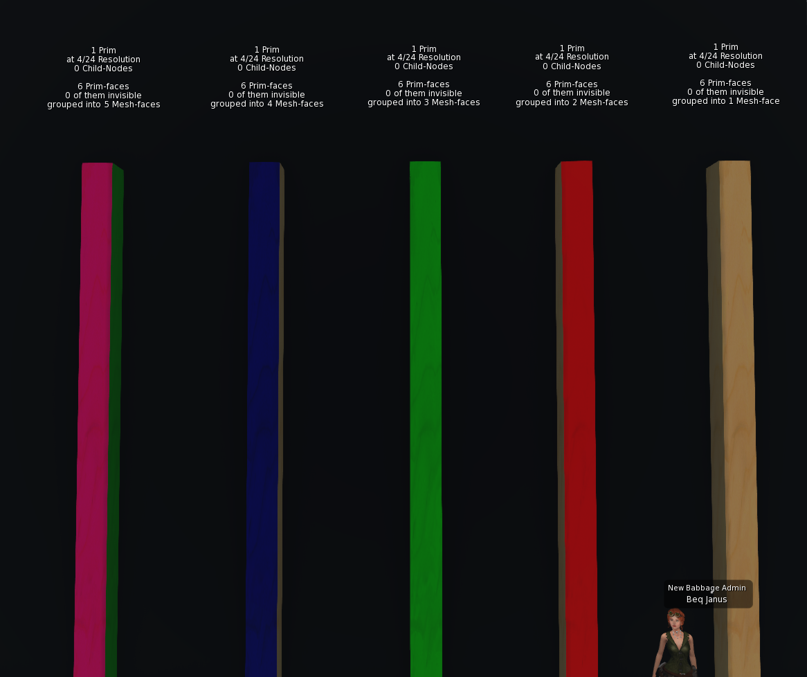
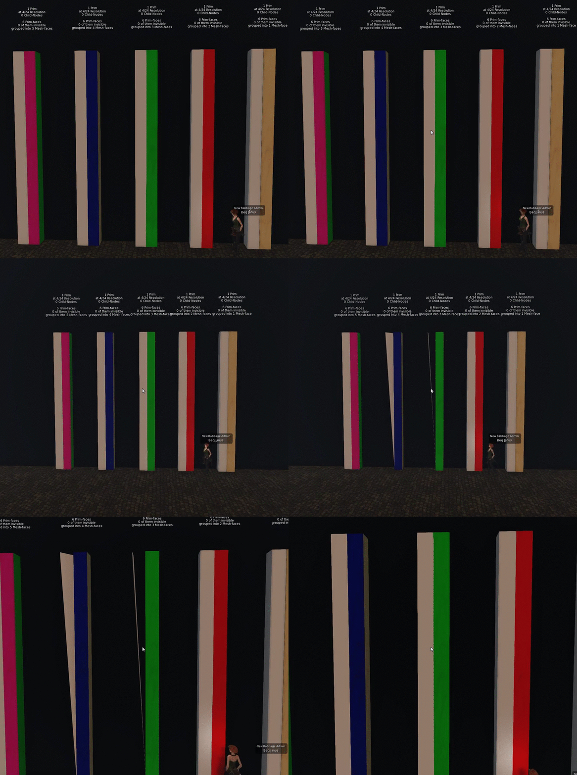
Summary: Due to a bug in the viewer, the bounding box for meshes with only 3 or 4 faces ignores the Z-axis completely.

You may recall that the bounding box is important when considering the transition between LODs. My 2012 blog post "Too much information" explains the role of the bounding box for those unfamiliar.
Given that the radius (r) is defined in terms of all the axes, if Z is dominant and then ignored, the effective radius is much smaller than it ought to be and as a result, the LOD transitions happen a lot sooner.

The demonstration is very simple. I created five identical Mesh columns using Mesh Studio (MS). I gave them each a different number of texture faces. Right to left in the image we have the prim models for one face through to five with the MS floating text to confirm this.

They were then each uploaded identically. The model was the HIGH and all other LOD models were minimised so that the object would collapse to minimal triangles as soon as the HIGH LOD went out of range.

Lining these all up alongside their prim equivalents and panning out demonstrates the issue very clearly as the following gif shows.
I hope that this helps make the issue a little more obvious and if you are only now learning, or being reminded of this, then please share as widely as you can so that people are not accidently impacted by it.

Bye for now

Love Beq
x

Thursday, 20 February 2014

So what are the laws of Physics?

I've been reworking the Mansard Roof on Maison Horta in Mesh. It is currently a sculptie created a year or two back using Sculpt Studio. The challenge is to get the LI low and have a reliable physics profile and resilent LOD. Nothing new there.

Sculpted mansard with sculpted stone dormas
 I detached the dorma and made a prim model using simple wedges for the most part. The final model being 13 prims with 5 distinct texture faces. I generated the Mesh using Mesh Studio and then switched to Blender. 

The Mesh Studio model

I knew that some of my joints were inaccurate, this was in part my sloppiness and in part lack of precision in the shear and taper options. Blenders remove doubles command allows you to merge vertices that are in close proximity and when used sensibly can tighten up all those poor joins.
Blender model - perspective makes the angles look wrong.

The Blender model can be further optimised, by hand editing we can eliminate unnecessary vertices that lie on un-attached edges (such as the top edge) and their associated geometry, the aim as always is to look for new ways to divide up the shape into triangles. Even now there are a few more savings that could be made but I prefer in this case to avoid long thin triangles.
Optimised by hand.
For medium LOD I can use my intimate knowledge of the use of the item to make firm decisions. The interior will never be visible from far enough away to drop to medium LOD, therefore I can cull all the interior faces. I make sure to keep a triangle with the correct material assigned though to ensure we comply with the basic Rule of SL Mesh that all LODs must share the same materials.

For Low LOD, I am going to use the same model as Medium. This will push up my streaming cost but so long as I stay under 1.5 I will be happy, and it will ensure that the house remains good looking for those spectacular New Babbage roofline shots that people love.

And so... physics. The point of this blog. In second life the laws of physics or not so predicatble as those in in real life. I've noticed this in the past but rarely taken the time to explore much. You may have noticed that when you import a Mesh the calculated physics cost in the upload dialogue is close to useless and this is true of both TPV and Lab viewers.

So how do we get the correct balance of physics shape to physics cost?

Given that my next article in Prim Perfect will need to examine physics, I decided to experiment. The first and simplest task was to use the model itself. In this instance it is actually a pretty simple Mesh so we'll see what happens.

Firstly, we specify the model as before and then for physics we select "Use HIGH". We will not touch analyse. As you can see the uploader predicts a physics cost of 0.440. Brilliant. All good then.

Using High LOD model, No analysis.

But when we get it onto the grid and rez it what we find is a different story...
The physics cost is not 0.44, it is nothing even close to that. The physics cost has rocketed to 1.4. It all works nicely though. But perhaps if we were to use the analyze function we'd get better results. maybe that elusive 0.44.

In the screenshot below we see the upload screen. This time we have selected the Analyse option. We are using the Solid method as in general this is best for block builds (use surface for curved builds). In pracatice you can try the 3 methods and see whcih gives the best (simplest) physics that looks right.
The analyse function has returned and told us that the physics mesh has be decomposed into 6 hulls. That seems plausible so we can accept that and go ahead with the import.
another aspect to note however. The Analyse function has pushed our import cost up. It is now going to cost us 13 Lindens whereas before we only paid 11. What is going on?

So now we have imported the mesh with our highly analysed decomposition, surely we must get better results in world....Errr no.

This is odd. We have used the self same mesh and rather than letting the system make some estimate (using an as yet unknown methodology) we have let the Havok system break up the mesh we provided into the most optimal collision shapes it can. The result, our physics cost has rocketted from 1.4 to 2.6 taking our overall LI from a rounded down 1 to a rounded up 3.

If a non-analysed collision mesh can be much lower (in some cases) how does that occur?  you might be tempted to think that the non-analysed collision mesh is inferior. Well it does not seem to be. I can happily walk back and forth through the gaps. But when we take a look at the Metadata view of the physics we see something very peculiar indeed.

Analysed Mesh with physics shape in blue
First, let's look at the physics model generated for the analysed mesh. A nice tight fit, and near perfect match to our physics template. This may be overkill for out needs but we'll come to that later.

Sure enough we can walk through the doors and if we walk into the wall we will slowly climb the slope or walk on the spot on the flat side.
 No surprises at all, physics mesh doing exactly what we expect, and a good job too given how much we are paying for it in LI.

Now, let's take a look at the physics metadata for the non-analysed physics.


Non-analysed mesh with physics in blue
Wait a minute, that's not what we asked for, that's not what we are observing either.
The physics shape revealed by the "render meta-data" option in the viewer is showing us what appears to be a default convex hull. But that cannot be right. I can walk through the doors and collide with the walls with the accuracy of the analysed mesh above, and yet the viewer is telling me that the physics shape does not even know about the doors.

Is this a viewer bug? I have not tried the Lab viewer yet.

trying to walk through with "convex hull" physics
The last couple of images show the difference in behaviour of the same object. Firstly with "convex hull", secondly with "prim". as you can see, with "prim" I can walk through the gap. This is not news... However, the physics shape is the same in both cases, you can clearly see that I am standing "inside" the supposed physics shape

walking through the same model but using "non-analysed" prim physics.


Time lapse video: Building using Mesh Studio

Hi all,
I recently made a free gift to accompany the February edition of Prim Perfect and the resumption of my Mesh creation articles. I decided to film the build and have since turned it into a shortish (10 minute) time lapse.
You can't really call it a tutorial, but perhaps it will show you how simple Mesh Studio is to use.

I have placed it on Vimeo.
https://vimeo.com/87133047