Showing posts with label LOD. Show all posts

Sunday, 20 June 2021

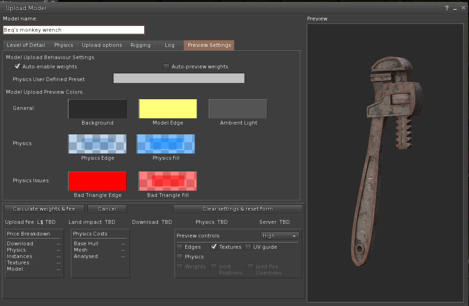
Summarising the next improvements to Firestorm Mesh Upload

In my last blog, I covered at length one of the changes I have put into the forthcoming Firestorm release. This post is a shorter summary of those changes and two other updates that I think will appeal to many mesh creators. 


1) Materials subset handling and related errors

For a full, blow by blow account read the previous blog, but in summary, the way that mesh "texture faces" are handled has been rewritten to give you more freedom in how your meshes are organised.

As best I can tell, there has been a bug in the Mesh upload parser (the thing that reads your Collada files and prepares them for upload to SL/OpenSim), so in-grained was this bug that most of us never realised it was a bug. We have all become accustomed to having to place empty triangles in every LOD model to represent the full set of material faces. Given a Mesh "house" whose High LOD model uses 5 materials, "frontwall", "roof", "door", "carpet", wallpaper", we might remove all the geometry from the interior faces for the lower LODs as you would never see those from the outside. However, creating "house_LOD2", as the medium LOD model with only the exterior materials present would result in the error, "Material of Model is not a subset". We would grumble that this was a subset, but with no way around this problem, dutifully return to Blender and add 2 stray triangles and assign one of the "missing" textures to each.  This is painful, time-consuming and frustrating but most importantly it is very confusing for new creators. It also has a further serious side-effect. the LOWEST LOD model is notoriously over-priced in SL, by which I mean that the cost of each triangle in the LOWEST LOD is so high as to make it near impossible and at best time consuming to produce a good LOWEST LOD model. For example, a small hand tool which due to its small size will rapidly be reduced to LOWEST LOD, can typically have no more than around 20 triangles before it starts to seriously drive the Land impact up. If you have to give away a number of these precious triangles just to please the grumpy uploader trolls then you have already lost a large proportion of your allocation. 

Form the next Firestorm release this will no longer be the case. With the exception of the high LOD model all the other LOD models can now have any valid subset of the High LOD materials, they do not even have to be a subset of the immediate parent LOD. 
Thus you can have the following structure
8 faces in the high LOD - A,B,C,D,E,F,G,H
4 faces in the Medium    - B, E, G, H
2 faces in the Low           - A, C
& just 1 in the LOWEST  - F

Or any permutation of these. The only requirement is that the superset of all materials used in all LODs must be present in at least one triangle in the HIGH LOD.

2) Ready-to-use physics presets


The physics shape tab on the mesh uploader is generally not well understood. This is in part because it is a technically complex thing, in part because the viewer has not helped as much as it could. I can't do too much about the former, though I've written a number of blogs that try over the years, the latter part I can do more with.

As of the next Firestorm release, creators will find 3 new options when selecting a physics shape.
1) The cube.
2) The hexagonal cylinder.
3) the user-defined mesh.

There tend to be two sorts of people when it comes to defining physics shapes, those that do and those that don't. For some items it is barely worth worrying about, for others it is essential. However, given that in SL it is often hard to predict how an item might be used once it leaves your protective custody, it does no harm to make sure it has a minimal physics shape that is broadly aligned to the volume of the mesh.

Many people will select the "lowest LOD", often some unrepresentative triangle. This will upload, but it means that once the item is rezzed inworld people cannot interact properly with it. A much better option for many items is a simple cube, and a lot of us keep a simple 8 vertex cube on our drives for just this. You no longer need to do this. The hexagonal cylinder is intended for items that are not quite so "cuboid".

I toyed with providing something vaguely spherical but came to the conclusion that any shape I came up with would fail to meet some need. So instead I added the ability to provide a "user-defined" physics mesh. This is a way to have a shortcut to that "shape you always use". It can be configured in the Settings tab on the upload floater. 


Some items require a custom physics shape, walls with doors and windows that you wish to allow passage through, for example. No defaults are going to help much there, but let me know if there are things that you feel would help. 

3) Ambient lighting in the viewport.

A couple of years ago, I changed the lighting in the preview window to make the three-point lighting work "better" but for some reason, things always remained dull and flat. Recently, it suddenly struck my partner Liz why this is. the ambient lighting is wrong. Upon investigation, it turned out that it was not just wrong it was "black". I have no exposed this setting on the "preview settings" tab so that you can change it, I have found a dark mid-grey about 33% grey works well and makes the lighting "pop" properly. It is especially useful when uploading with textures.

At the time of writing, there are two minor niggles that I may change before release. 
1) It still defaults to black. I considered this as a good plan but given that anyone upset by better lighting can change it to dullness again I think I will change the default to something sensible.
2) When you change the control the preview will not update until you either pan the model or reopen the uploader. I may not be able to fix this immediately.

I hope these three sets of changes improve the quality of the uploading experience for you as much as they have for me.

Take care.

Love Beq
X

Saturday, 20 January 2018

For LOD's sake stop!

TLDR; Increasing LOD Factor increases lag. Just say no!

Introduction - Bad design is slowing you down.

Is your Second Life slower than you'd like? Do things grind to a halt when you visit a busy region?
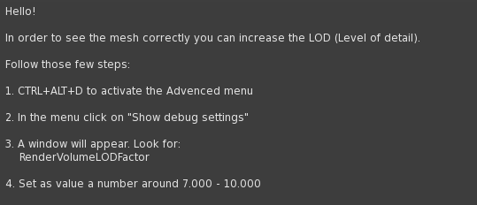
Have you read a notecard like this and followed its advice?

These things may well be related. Notecards such as the one above are sadly widespread, and I suspect that in many cases the designers suggesting this don't fully appreciate the impact their advice can have.

Higher LOD Factor = Lower FPS. 

Let's be very clear, the higher this LOD Factor setting, the longer it takes to draw the scene (frame), which means fewer frames per second (FPS). Lower FPS is a part of what many people call lag.

In the new release of Firestorm (5.0.11), the viewer will warn you if you have unusually high settings, and settings that are considered too high for general use will revert to defaults after a restart. This is done in the hope of improving the overall user experience by encouraging more creators to design efficient, well-behaved content. In 5.0.11 the limit for "normal" use will be 4; this may reduce further in the future.

The remainder of this post will try to de-mystify the "techie" terms LOD and LOD Factor and discuss why you should prefer content from creators who take the time to make Second Life–friendly products.

What is LOD?

LOD is an acronym representing "Levels of Detail", a standard mechanism in computer graphics that is used to reduce the amount of work required to draw a scene by using simpler forms of objects that are smaller or further away. The faster a single scene can be drawn, the more times per second it can be redrawn and the faster and smoother your in-game experience will be.

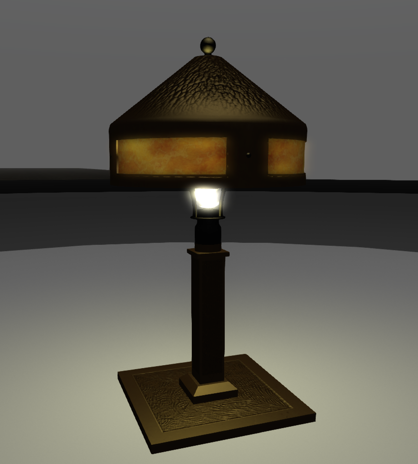
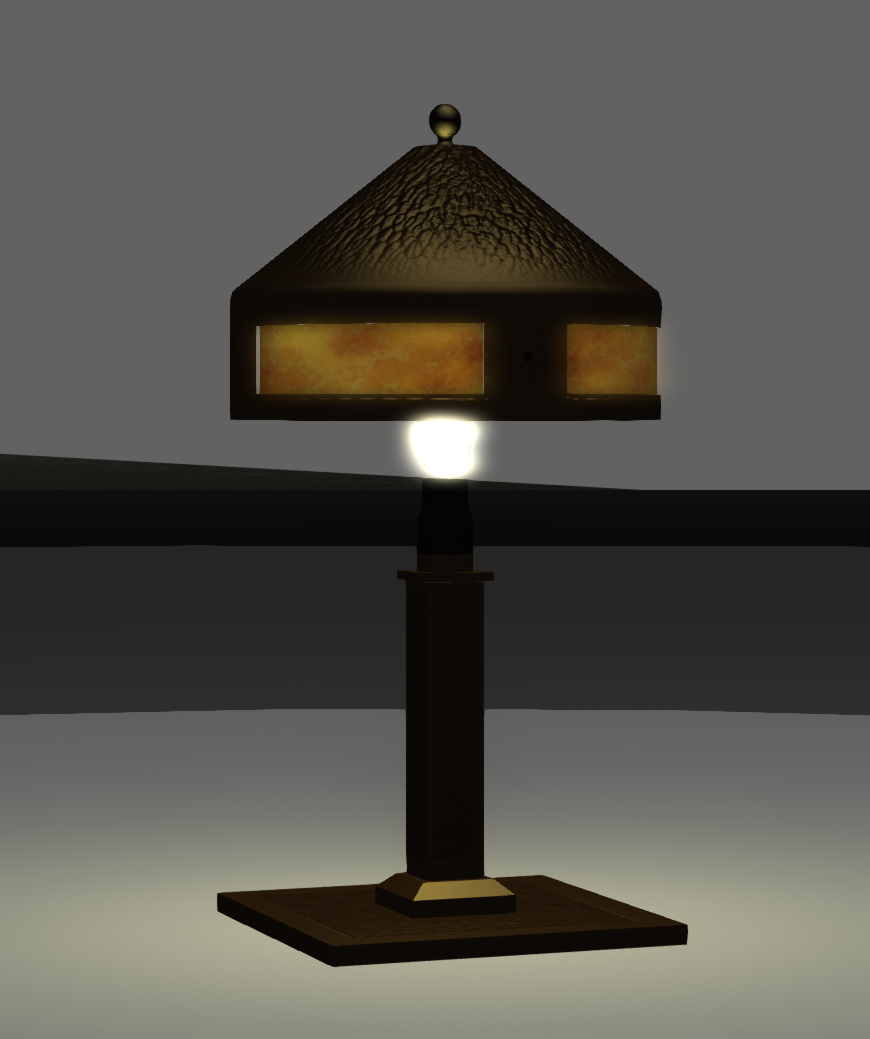
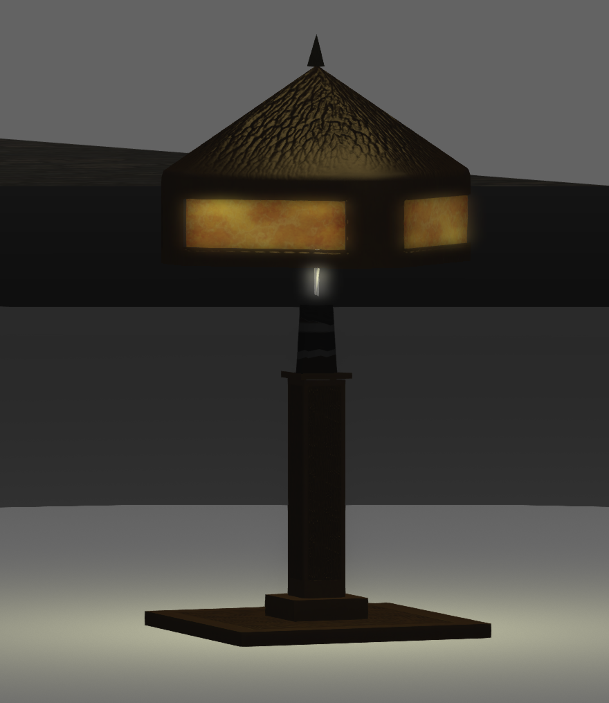
In Second Life objects are constructed from up to four versions of the same item, each with fewer details than the preceding one. These are the Levels of Detail (LODs), and you might see them as the object moves into the distance.
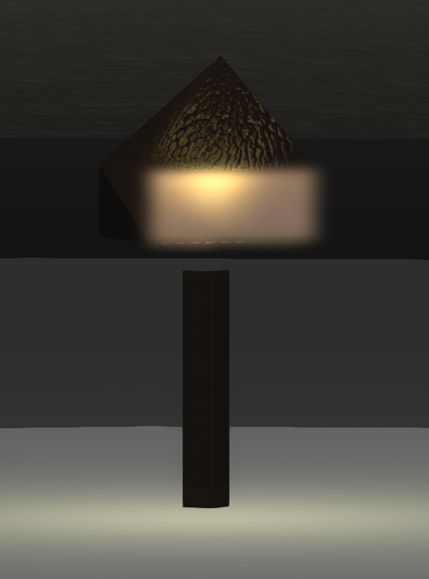
High LOD (2700 triangles)

Medium LOD (692 tris)


Low LOD (313 tris)


Lowest LOD (14 tris)

Each of the above shows a different level of detail for a 1920s style lamp made by me (click them to look closer.) 

How does LOD work?

As Loki Eliot once stated, the best way to visualise LOD is to consider a series of concentric rings around an object; as the camera passes from one ring to another the viewer changes to the next LOD model.

Here, with Loki's permission, is an animation of his original illustration.

As you can see, the further the viewer is away from the object the simpler the representation. The illustration exaggerates for effect, of course, and a well-designed object should decay gracefully as it vanishes into the distance.


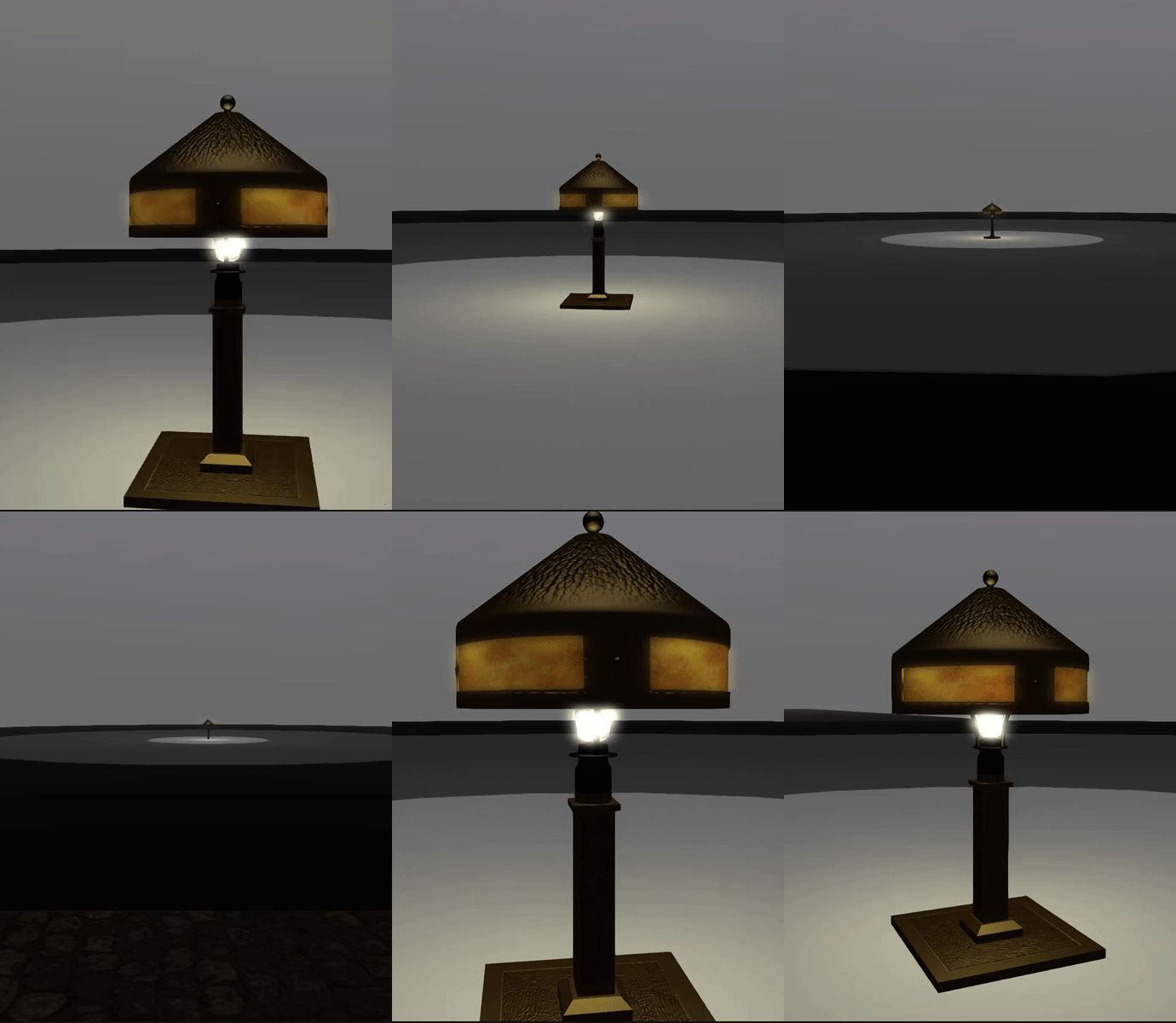
This second short animation loop shows a real object, the same table lamp that was shown above in its constituent models, this time viewed in-world on a platform of rings that represent Loki's concentric circles.

The viewer can be seen switching between these versions as the camera retreats away and approaches again.


The embedded image barely shows the changes at all; when viewing it full size, the switch is noticeable, but not so much as to distract you if you were focussed on nearby objects. 


How is LOD used?

It is the job of the creator of an object to specify what an object looks like in each of these simpler forms when they upload it to Second Life. A well-designed product should be recognisable at a distance, and the changes between models should not be so noticeable as to distract the user.

To encourage good design behaviour, and prevent someone setting all the LOD models to the same high detail version, Linden Lab levies a higher Land Impact penalty on objects with more complex, lower-detail models. The idea was to reward efficient object design with lower land impact. It never quite worked out

Where did it all go wrong?

Many creators understand how their creations affect the user experience and carefully craft models for each LOD to ensure that the user experience is good. However, for a long time now, there has been an unfortunate tendency with some designers towards skimping on the low detail models (often specifying just a single triangle) to artificially lower the Land Impact and make them seem "more efficient". This, of course, means that the object will crumple quickly as you move away from it, so they compensate for this by telling the users to "adjust their settings" to "see the product as intended." This has a significant impact on the overall performance capability of Second Life.

What is LOD Factor?

Remember those concentric circles I mentioned above? Each circle represents the boundary line either side of which a different LOD model is shown. How far away those boundaries are from the object is controlled by the size of the object and a thing called the LOD Factor. Irrespective of the size of an object, the larger the LOD Factor, the further apart those rings will be, and the wider the area that the models are visible for. With LOD factors that are high, everyday objects are drawn in "full detail" even if they are barely visible on the screen.

Why is changing LOD Factor so bad?

The LOD Factor setting is a global adjustment; it affects everything that you see. Every object in view, no matter how large or small, will have its LOD behaviour altered according to that setting.

By the act of setting an arbitrarily high LOD Factor, because your favourite sofa at home crumples when you stand by the door, the viewer will be forced to draw the high detail model for all objects a lot more often. Consider the extreme case of a jewelled earing worn by one of the crowd in a shopping mall, perhaps no more than a few pixels on your screen. In spite of the size, the viewer will have to try to draw every facetted jewel and tiny metal clasp just because a designer was unwilling or unable to design a proper LOD model and told you to use a debug setting instead. 

How do you find better content?

"Ok, ok, enough already, I get it. Bad content, has bad LODs. But how do I find the good stuff?"

One simple rule of thumb is to avoid content that tells you to adjust your viewer settings to see it properly. If an object comes with a notecard or other "advice" to increase "RenderVolumeLODFactor", then the chances are that the object will not have well designed LOD models. However, with the new release of Firestorm, you will also have better tools and be able to inspect an item in-world to see exactly how it behaves.

The new Mesh Info panel is described in my previous blog post. Using the LOD display function, you can look at the different LOD models, and in the information table, you can now also see what distance the concentric LOD rings would be at for both LL and FS default LOD Factor settings.

When evaluating an item, consider the way it will be used. Outdoor objects such as cars are likely to be seen from far greater distances than a piece of furniture, and remember too that even if you adjust your LOD Factor higher, your friends may not and will not be so impressed by the pile of crumpled triangles parked outside.

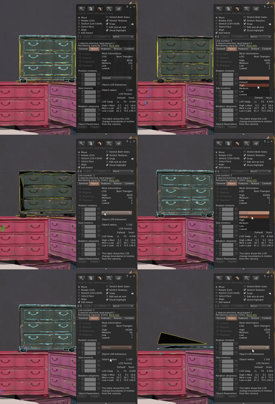
An indoor item may never be expected to be seen outside of a room so the designer may have made legitimate choices to economise, use the tools to decide. The chest of drawers in the image to the right will start to collapse at 5m for anyone on the Linden Lab viewer default settings. In a small house this is fine, but in a stately bedroom this may not be so desirable.

Will this situation change?

I hope that with these changes people will be empowered to start to take control of their SL performance and make better choices, but there is a stronger incentive too. As Second Life continues to grow and evolve, new features are being added and old features modernised. With each new development, there are extra demands on the viewer to draw them. To balance this equation and to keep the world accessible to as many as possible, more needs to be done to encourage efficient Second Life optimised content. There are very strong suggestions that the way that Land Impact is calculated will change, penalising poor content in favour of well-designed content. How this will be achieved is as yet unknown, but the writing is on the wall for bad content.

I hope this has helped to explain a complex and somewhat technical topic without too much techno-babble.

See you soon.

Love 

Beq.
x

Tuesday, 31 October 2017

Coming to Firestorm soon... A couple of new features for builders and non-builders alike.

There is a new Firestorm slowly working its way through the pre-release testing process, there's lots of goodness in there that I'll not cover here but I'd like to highlight a couple of features that I have added for builders but which I feel will help other users as well.

Physics view while editing objects.

Regular Readers of my blog will know that I love the physics view in "Render Metadata" for its valuable debug capability. You may recall that I "fixed" a subtle bug in that which prevented us correctly debugging certain "thin wall" problems and that change will be part of the new release. The debug physics view has a couple of major drawbacks, the first is that switching to it is clumsy and slow, requiring that you have the developer menu enabled, the second is that everything gets coloured whether you like it or not, making it difficult to see what is going on.

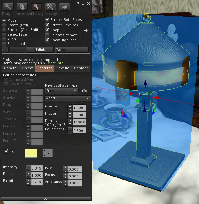
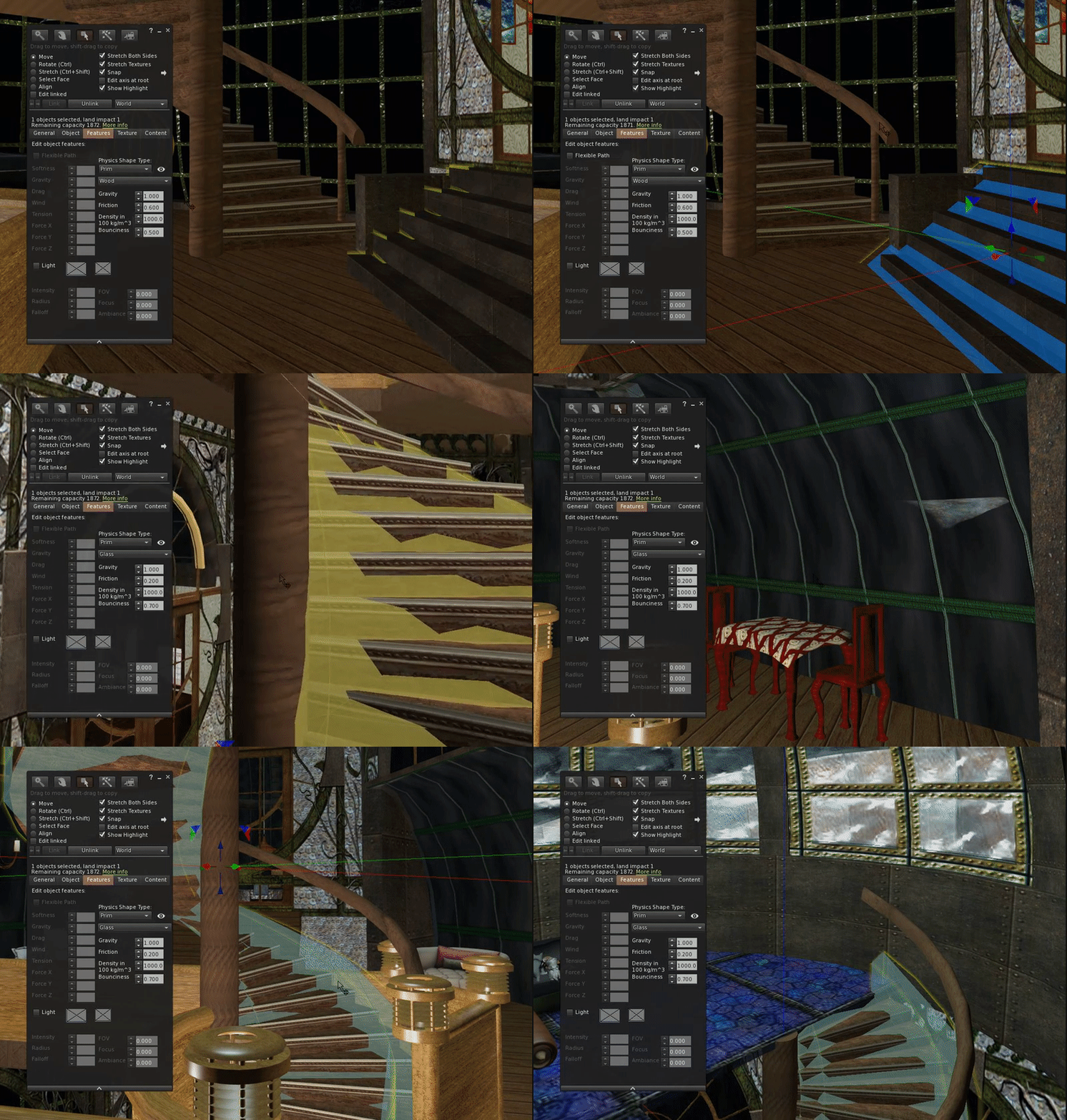
To address this I have added the ability to show a physics outline for the object that you are editing.
The functionality is accessed from the features tab in the edit dialogue and is represented by an "eye" next to the physics selection combo box.

Clicking on the eye will toggle it on and off, showing a representation of the physics shape as shown in the example here.

Once this mode has been toggled on, it will remain enabled when editing subsequent object unless toggled off;  it will, however, revert to being off after the next login. This is deliberately done to prevent it confusing users who enable it in error and forget how to disable it.


Mesh information in the object panel.

When you edit an object you will be used to seeing information in the object panel. On the left-hand side, the properties common to all objects. The position, scale and rotation.

On the right-hand side details specific to the type, the hollow, cut and taper etc for prims, special features like dimple and hole size on a sphere or torus respectively. For sculpt maps you'd often see the rainbow hues of the sculpt map texture, but for Mesh, nothing. In fact, worse than nothing because you'd get some greyed out leftover fields.

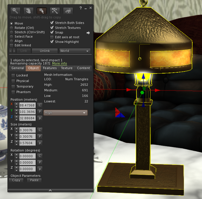
In the new release, however, I have started to address this and have added a Mesh specific information panel that shows you a couple of extra details about the object and also allows you to artificially see what it will look like at a distance by selecting the Level Of Detail.


What does it all mean?

The new physics mode operates in a very similar manner to that given in this more technical blog from a few days ago. In essence, the shape tells you exactly where your avatar and other objects will collide with the object. The colour tells you when the physics "cost" is very high. 

The Mesh info panel tells you how detailed each of the levels of detail in the model are by listing the number of triangles used to make ir, it then allows you to preview the LOD models. 

OK, but really, what does it all mean? Why do I care, I don't even build stuff?

For non-builders there are a few notable benefits. 


Fix those pesky "stuck LODs"

Firestorm "LODv iew" FTW from Beq Janus on Vimeo.

Sometimes, perhaps you've been cam shopping, taking photographs or maybe even perving on your neighbours, then when you "snap back" to your room you find that your clothes are not rezzing properly. There is now a "simple" fix.


1) Find your inventory window and select the worn tab
2) right click the item, and select edit. 
3) Click the object tab, and "edit linked"
4) click the broken item
5) It magically repairs itself

But that's not simple enough I hear you say... We agree and so by the time the new Firestorm is ready for release we hope to have simplified this trick into a one-click fix in the menus courtesy of our lead developer Ansariel.

Why can't I rez on my mesh table/floor/bed.

You know the feeling, you are late to a party, you grab that awesome Gacha "rare" from the reseller on MP. Of course it comes boxed. So you quickly drag it on to the floor....your brain catches up, but it is too slow to stop and your finger releases.... "Can't rez here" says the little pop up. What's worse, your dress is gone and won;t come back until you relog, it may take longer. 

We've all done it. Rezzing items can be a little hit and miss at times but did you ever stop and wonder why? The answer is often simply "laziness". Your special outfit just got eaten by the Linden void because the designer of your house didn't give it a proper floor plane. But it is not just floors, chairs and all manner of objects that you might conceivably drop an item on weren't made with a proper physics shape and even though it tries it's best neither the viewer nor the sim can work out where to place your item and ultimately it gives up. Well now you can find out where the safe spots are.

The physics shape view let's you see how the simulator sees the items when it is trying to work out where to place things, where you walk and how things collide. 

This short video shows the problem with a simple table (deliberately badly made by me!)
Physics View Mini Tip from Beq Janus on Vimeo.

Why do I sink in this floor? Why do I keep falling off the stairs

Of course, physics is used to decide where you can and cannot walk, and even for the non-builder, sometimes it can help to understand why your feet pass through the stairs.


Friday, 20 October 2017

My life in lamps...

As I noted in my previous blog I finally got around to creating a set of items for sale. The Antique Radiators were the "sale item" for the Decennial event but I also needed a hunt item. The theme of the hunt is Timeless, the event and the hunt celebrate 10 years of Fallen Gods in Second Life, so I wanted something that also meant something in the theme of time and growth. The item I chose will be familiar to those who have known me for years or who have read my articles in Prim Perfect.

Back in 2007, I made myself a lamp, based on a rather lovely Arts and Crafts period design from the Roycroft movement. A simple but elegant design that could work as a low prim lamp for my undersea refuge in the Vernian Sea in New Babbage.


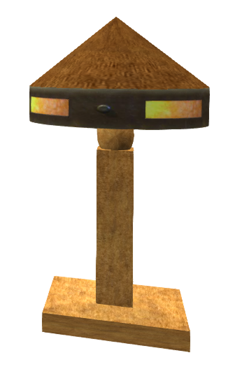
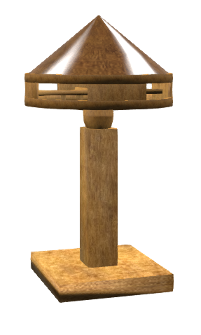
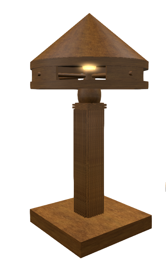
The very first version is shown here on the left. A gloriously extravagant 8 prims, 2 of which were a bizarrely flickering animated candle flame where the bulb should be. The rim texture cut from a photo of the lamp in RL and recoloured to look as though it was lit up.


As SL and I both grew, I rebuilt it in around 2008 using "the latest technology", reducing the 8 prim lamp to a glorious 3 prim sculpty based model (right).

The lamp was more or less identical in form to the prim version and created using an Inworld sculpting tool called SculptCrafter which in its way (despite being made by a different person) was a forerunner to tools like Mesh Studio, converting prims to sculpts, which it spat out in chat as a uuencoded text stream which you pasted into your preferred decoder to get the expected sculpt texture. A really neat solution to not needing an external service in fact.


Then in 2012, I was asked to write articles for Prim perfect, demonstrating that Mesh and prim building were not necessarily at odds, the articles built upon a blog post I wrote on inworld mesh creation for which I built the version on the left. The model was created using the excellent and highly under-rated Mesh Studio. The project was a little artificial I added heavy metal fluting to the sides of the stand giving it a more Art Deco feel than theo original RL piece having challenged myself (and the tools) to improve upon the 3LI sculpty in both looks and land impact. The lamp was also used to explain generated LOD models and how handmade LOD models are essential to really efficient and well-structured meshes.

The result was a credible (I think) demonstration of the tool, taking a detailed 110 prim model with all my metal fluting and additional details and producing an efficient 1LI Mesh with Strong LOD characteristics.

It's been five years since that project; we've seen the introduction of many new features, materials being perhaps top amongst them. And I have started to confront my personal daemons, tackling my insecurities around artistic ability to improve my texturing skills, face down the fear of Blender and it's mythically horrendous UI (hint: it really is not anything like as awful as people will lead you to believe, it just takes a little practice). And so it seemed fitting, that to celebrate 10 years of my friend Alia's wonderful creations, with a nod to my own 10 year anniversary too, that I should once again update the lamp.

The 2017 Roycroft style lamp is available as a hunt prize during the timeless hunt and may become available later from the Verdigris store, in a variant form.

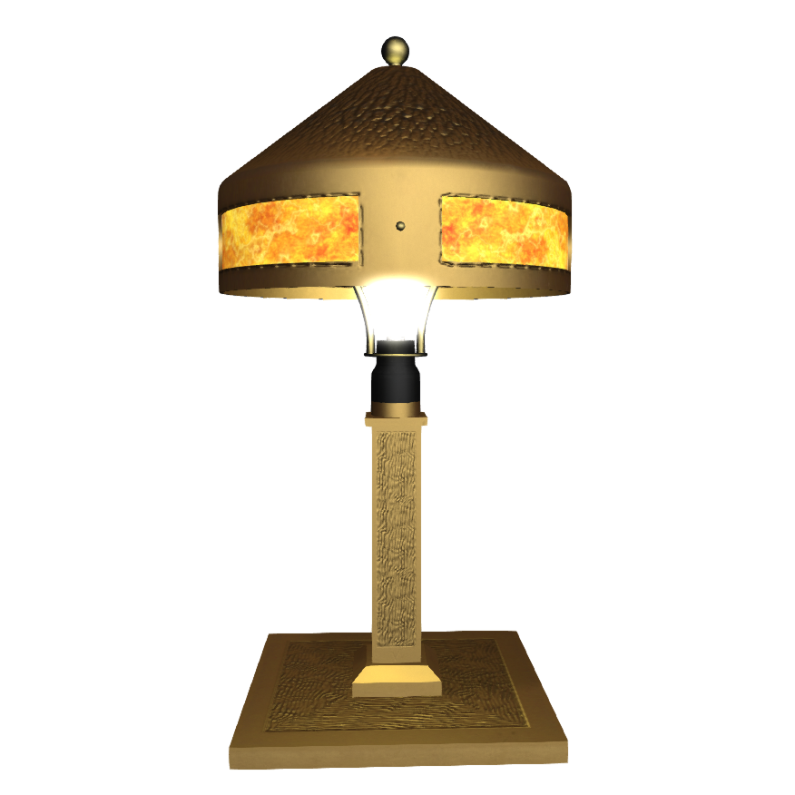
At 1LI, we now have a lamp that retains much of the hammered effect detail of the Roycroft originals. The detailing employs Normal maps for those with Advanced Lighting, but also bakes and additional Ambient occlusion to the texture to give some of the effects to those without that feature.
Materials are used for the bakelite bulb holder as well as the metallic lamp itself, and the mica panels use the emissive mask feature of the diffuse texture to give a more realistic glow when the lamp is turned on. It was important of course that in an item of this scale it retained its shape and volume as the LODs decayed, which became a little war of attrition when the lamp nudging over the 1LI threshold.

The Decennial event and the excellent Timeless hunt are still open and I would encourage you to pay a visit.


Sunday, 9 October 2016

Not as simple as it looks...

A little bad news

In my last post on "bug hunting", I talked about the LOD decay issue and a potential fix. I said in the blog that "subject to QA" it would be coming to you soon and sure enough QA found an issue. It turns out, rather a large issue given that as a result of my fix a lot of mesh textures get utterly corrupted. Needless to say, that patch was backed out. Thanks to Ansariel Hillier and Whirly Fizzle from the Firestorm development team for spotting and doing some initial troubleshooting of it for me while I was overseas.

It is not all bad news

The good news is that I have submitted a new patch that uses a completely different method. It is a method that I shied away from first time as I felt it was too close to the critical path, i.e. a part of the code that has significant impact on the overall performance, and chose to make changes far earlier. I am happier with the new solution, it is simpler, more elegant in some ways, and overall improves the performance ever so slightly by avoiding some convoluted checks when calculating the LOD for Mesh.

This patch has also highlighted the rather bizarre dependency that a mesh has on the legacy prim definitions and adds weight to my request for documentation on why this is done. Once I have cleared a few other loose ends up I may well circle round and have a look at this again.

On a related note. Complexity and confusion

With the recent introduction of complexity limits to the viewer has confused some people and highlighted certain bad practices in Mesh creation. However, due to a range of different "features" it is still not really as reliable as anyone would hope. Part of this is down to the fact the rigged mesh does not have its LOD calculated in the same way. 

In fact, for worn, rigged mesh the LOD is not based upon the radius of the object but is instead tied to the bounding box of the avatar that wears it. This is a quite deliberate choice, explicitly mentioned in the viewer code,  and means that if you wear a Mesh body and Mesh head and Mesh hands, that they ultimately LOD swap at the same time, rather than the hands decaying first (being the smallest) then the head and later the body but it also means that the complexity calculations need to consider this (which they do not at present). This means that those super high poly onion skin mesh head that melt down your graphics card in a busy sim, are only getting a complexity score based on the apparent scale and yet they are visible based on a much larger scale. Once you realise this...you can then read my Jira here because it is actually worse than that, rigged meshes are being given a far far easier ride that they deserve.

All this being said, it is what it is and changing this stuff is hard because it breaks things. So the Lab are looking at pulling together all the oddities in the LOD and complexity calculations and reviewing them to see what if anything can be done to make the complexity numbers more meaningful and usable. There is no timescale for this, just an intention to review things at the moment. I for one will be keeping a keen eye on progress.

Love 

Beq
x

Saturday, 1 October 2016

Bug hunting - Fixing an ancient LOD issue

Those of you who may have read my blog post in July, "Tell your friends - An old bug that people really ought to know about." might be interested to know that I have made a lot of progress towards fixing it.

TL;DR

The long-standing bug discussed in the blog (see link above) that impacts the way that certain Mesh objects decay their LODs has been identified and fixed. I will be submitting the patch to Firestorm and other TPVs where applicable and back to the Lab so that (if it is accepted) we can be rid of this pain in the posterior.

Introduction

After having suffered and grumbled at this bug for a long time I decided to bite the bullet and for the first time since about 2009, build and debug the viewer. After a week or so of digging around and working out how V3 viewers hang together, I now have a solution to the problem we observe, but it still needs to go through QA and of course the thing I cannot know...why did it do that? More of that later...

The basic problem

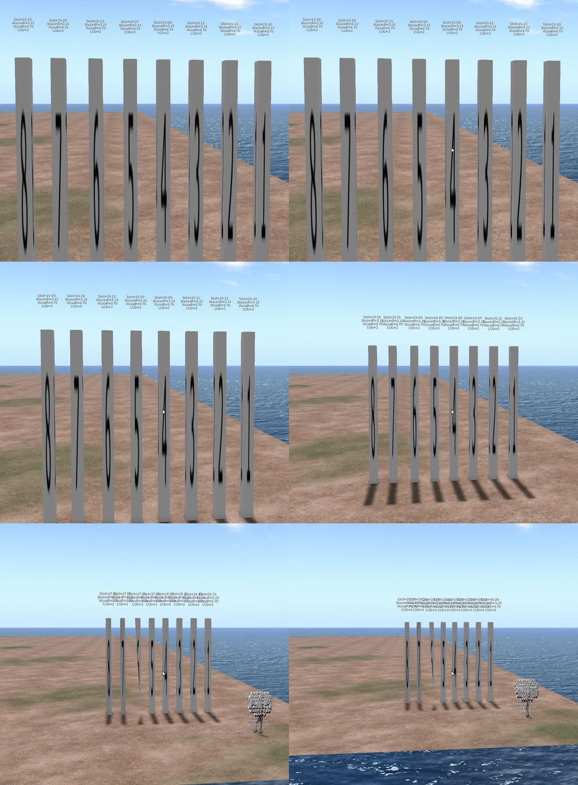
Here is the basic problem as we originally observed it.

Any mesh object with either 3 or 4 texture faces will crumple earlier than an identically sized mesh with only 2 texture faces.

But in fact it is worse than that (a little).

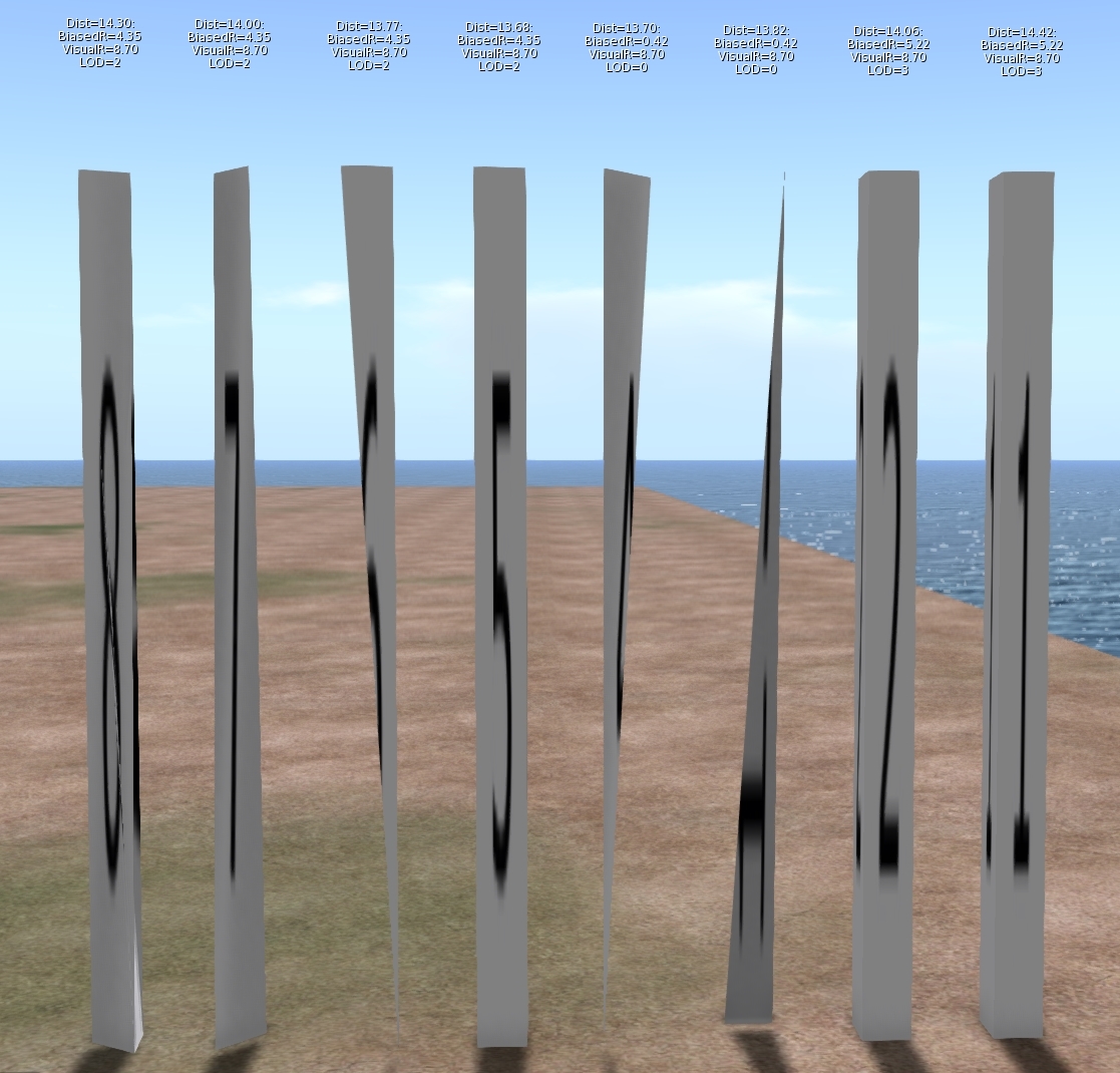
As I dug into this problem it turns out that this is not a problem that affects 3 and 4 materials only, it just affects them worse. Meshes with 5, 6, 7 & 8 material faces will also collapse earlier than the comparable 1 and 2 material versions. The following image will illustrate

The image shows 8 identically sized columns. Under normal circumstances, one would expect these to look identical and change LOD at the same distance from the viewer. The textual display above each shows the following:
Dist:                   The distance of the object from the viewer.
Biased Radius:   An adjusted radius based upon a biasing algorithm, the source of our woes.
Visual Radius:    The "True" Radius defined by the bounding box of the object.
LOD:                  The Level Of Detail currently shown. 3=HIGH, 2=MED, 1=LOW, 0=LOWEST

The display is a bug fix/enhancement of my own and if accepted will appear in a future viewer. It is a change to the existing Render Metadata -> LOD Info which is basically broken on all existing viewers. I should also note that I use the term radius here, because not only is it the term we use inworld when examining the LOD equations, but it is also used in the code, all of which is despite the fact that it is not the radius at all but the long diagonal of the bounding box!

As you can see, Objects 1 & 2 are still at LOD 3, even though their distance from the camera is marginally more than the others. Further scrutiny of the hovering figures shows that the Biased Radius is 5.22 compared to 4.35and 0.42. Objects 3 & 4 have collapsed to LOD 0, with a biased Radius of just 0.42 they had little hope of remaining visible. While all the others have decayed to a slightly withered LOD2.

But why does this happen? To understand this we need a little implementation detail.

What does a mesh look like on the inside?

SL is often criticised and even rubbished for the way it does things, but if I am really honest I have a great deal of admiration for the general architecture. For a system design 15 years ago it has managed to grow and adapt and shown remarkable durability. The code certainly bears many battle scars and the stretch marks of its adolescence glare an angry red under scrutiny but the fact that it has gone from super optimised prims through to industry standard Mesh, growing as and when the technology of its users was best able to adopt it is very impressive. 

Second Life has achieved this longevity through a series of "cunning plans" which have extended the capability without altering the infrastructure drastically. all the objects in your inventory have a top level structure which is basically a legacy prim, extensions have been variously grafted on to this but leave behind the traits of the original prims. This means that, even though they are unused, a mesh has a slice, taper and cut setting as well as many others.

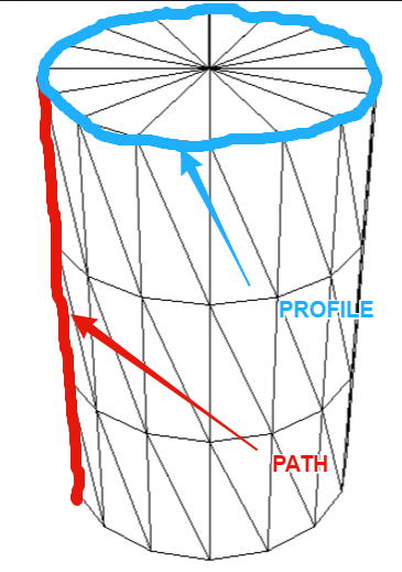
These top level prims also denote what type of prim they are, cube, sphere, cone, etc. and Meshes are no different. The basic shape is determined through two parameters the PATH and the PROFILE. Thus a sphere has a PATH and PROFILE of CIRCLE, while a cylinder has a PATH of LINE and a PROFILE of CIRCLE. Sculpts came along later and are indicated by the presence of a sculpt parameter block on the end of the Prim. Perhaps surprisingly Mesh is denoted as a type of Sculpt with the "SculptType" is set to the value 5 representing Mesh.

This allows the "cunning plan" that the settings for a sculpt can be reused. In a traditional sculpted prim, the SculptID holds the asset server UUID of an image that defines the sculptmap. In a Mesh the same field is used to hold a UUID of the underlying Mesh. It is important to note here that the Mesh that you upload is given this UUID that is the "child" of the Mesh object. You never actually get to see or know the underlying Mesh asset ID inworld.

So we now know that a Mesh is really a legacy prim, denoted as a sculpt, whose map is redirected to a Mesh defintion. So let's see where it goes wrong.

LODScaleBias and the legacy impact.

My first task in trying to fix this bug was to start to map out the viewer. It has been at least 6 years since I last looked at the viewer code and back then I was only really building it for my own purposes. The code has all the hallmarks of mature and much patched and extended code and is a bit of a rat's nest at times, but nestled deep inside the nest is a function simply called calcLod()
This function, along with the name, also was home to the output for the Render Metadata->LOD Info function.

The Render Metadata services are a set of great tools for builders and developers who are trying to understand a problem, those who have read this blog in the past will be well aware of the physics display. The LOD Info display has been a bugbear of mine for some time, I have never been able to work out what it was displaying, It would show a number that would typically not change with the LOD display and was to all intents and purposes useless. It turns out that is exactly what it is. At some point in the past it appears to have been borrowed for some other purpose and upon examination had nothing to do with the LOD at all. The damning evidence was a commented out remnant of the original call. My first "fix" of the expedition was, therefore, to make this function more useful, the new display is shown on the left. I will be submitting that patch separately.

Back to our friend calcLOD().
I won't post the code here, it is too long but the function does what you would expect it to do given its name but the devil is in the detail.

BOOL LLVOVolume::calcLOD()
{
F32 radius;
F32 distance;

if (mDrawable->isState(LLDrawable::RIGGED))
{
// if this is rigged set the radius to that of the avatar              
}
else
{
distance = mDrawable->mDistanceWRTCamera;
radius = getVolume() ? getVolume()->mLODScaleBias.scaledVec(getScale()).length() : getScale().length();
}
.....etc etc
}

There are a couple of interesting diversions in this function, the first we covered above, the second is a special clause for rigged attachments which deliberately adjusts their LOD scale to be that of the avatar that is wearing them. This is the subject of a Jira and is likely to come under scrutiny in the current quest to improve complexity determination.
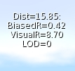
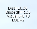
However it is the code in bold and further highlighted that we care about. What is this LODScaleBias? Our amended LODInfo display proves that this is the culprit. The BiasedRadius of a 3 face Mesh is shown on the left and can be compared to the same mesh with 6 material faces shown in the example above. 0.42 when the true radius is 8.7, no wonder the thing crumbles. 

Digging deeper we can identify where the LODScaleBias vector is initialised. 
BOOL LLVolume::generate(){
...snip...
    mLODScaleBias.setVec(0.5f, 0.5f, 0.5f);
...snip...        
    if (path_type == LL_PCODE_PATH_LINE && profile_type == LL_PCODE_PROFILE_CIRCLE)
    { //cylinders don't care about Z-Axis
        mLODScaleBias.setVec(0.6f, 0.6f, 0.0f);
    }
    else if (path_type == LL_PCODE_PATH_CIRCLE) 
    {    
        mLODScaleBias.setVec(0.6f, 0.6f, 0.6f);
    }

 ...
So here we have it.

"Cylinders don't care about Z-Axis"

The code above sets up the bias. The default bias is <0.5, 0.5, 0.5> and I'm feeling rather stupid now because having said previously that Radius is not really the radius...if you take the long diagonal and half it then of course you do have the radius (the radius of a sphere that encloses the bounding box, at least.) We then get to the code in bold red. Here we find that if the legacy prim has a linear path and a circular profile then it must be a cylinder, 
The image to the left shows my hand drawn annotation of what those two parameters mean. Anyone who worked with prims will most likely understand the terms.

This does pose a couple of questions, the most obvious of which is:-
"Cylinders don't care about Z-Axis" WHY!!!!?

There seems no logic to explain why a cylinder would be set to LOD quicker. Clearly, when used as a column it results in a high number of long thin triangles but does that really warrant such punishment? I have enquired with a couple of Lindens to see if we can get some clarification on the history of this.

Noting the <0.6, 0.6, 0.0> when applied to our example mesh columns give a Radius of 0.42 we can confirm that this is , as had been suspected, how out poor Meshes are being evaluated, and so the second most obvious question is:-
Why is my Mesh arbitrarily being branded as a cylinder? 
Again there seems no rhyme nor reason to the 3 and 4 material face meshes being treated this way. If the lab responds with an answer to either of these I will post a blog to share the info.

Having determined why we have this issue we need to go and find out where. At first, this seemed a daunting task. Somewhere in all the viewer code was a single line or two that was initialising these parameters incorrectly. I decided to start at the very beginning. The beginning for any asset is when it gets sent from the server to the client, a little hunting and we find a function that is called to process and unpack an update message for an object. In this code, I found the point at which the parameters are unpacked and placed some additional logging to print out the settings. 

Lo and behold the viewer is not to blame at all. The Object is already tainted before it arrives. This means that something is happening on the server and it would seem to be deliberate. 

How can we assume it is on the server? 

We have in previous blogs examined the Mesh Asset upload format and can note that there is no room in there for the legacy parameters. Moreover, that asset is the data that is referenced as the "SculptId". The Containing/parent prim is different, it is created on the server side, presumably during the validation of the upload process, the initilisation of the parent object must be assigning default values based on certain consistent criteria and as such results in the problem. As with the above, I have asked the lab whether they can confirm the reason for this, primarily so that we can understand if there are any side effects.

Having noted that Meshes are already tainted I added code to list out the types of Mesh and using a conveniently empty sim on the beta grid Aditi I created my series of 8 "identical" meshes.
the result can be summarised as follows.

# faces
PATH
PROFILE
BIAS
1
CIRCLE
CIRCLE_HALF
<0.6,0.6,0.6>
2
CIRCLE
CIRCLE
<0.6,0.6,0.6>
3
LINE
CIRCLE
<0.6,0.6,0.0>
4
LINE
CIRCLE
<0.6,0.6,0.0>
5
LINE
EQUALTRI
<0.5,0.5,0.5>
6
LINE
SQUARE
<0.5,0.5,0.5>
7
LINE
SQUARE
<0.5,0.5,0.5>
8
LINE
SQUARE
<0.5,0.5,0.5>

That is the end really. With the fix in place the Meshes quickly resolve and the new LOD Info display confirms that the Bias is no longer unfairly having some meshes. As for side-effects, we only modify at run time, and nothing is ever saved back to the server. Moreover I have implemented this to be configurable and should any issues arise it could be easily disabled. 

So what next? 

I am no cleaning up the code to remove or at lesat comment out any of the debug logging I used. I will then create a submit a patch to Firestorm. Having spoken to Oz Linden, I have been asked to sign a contribution agreement, this is a form that protects the Lab (and thus all of us) from me giving code and then claiming some licensing later.Once I have that in place the lab can accept my change and would then consider it. So that means that subject to QA and testing to follow hopefully we can put this bug to rest once and for all. 

It leaves a few loose ends. 

Why does a Cylinder ignore the Z? I just want to know.
Why does the server do this and will/should the server-side get fixed?
Would fixing this on the server make a difference to the SL Map

That's all for now, I shall leave you with an animation of the FIX in action,

Love

Beq
x
Saturday, 17 September 2016

How low can you go? An optimisation war story - Part 1 HIGH LOD tuning.

Einstürzende Neu "Babbage" bauten

A bad play on words to start a long blog :-)

When I walk around my beloved New Babbage I see far too many new Mesh buildings that collapse into a garbled mess as soon as I put my settings to anything close to that of a default user. Older buildings that are sculpted I can understand but with Mesh there is not really a good excuse.

So ask yourself, are you guilty of not paying attention to the "other" LOD models?

One of the drivers towards this is keeping low LI and an assumption that creating a proper LOD model away from the HIGH LI is both a lot of work and costly in terms of LI. In this short series, we will discuss a recent project and some of the strategies I used to meet a low LI target and ensure that the object remains visually consistent but more important a viable solid silhouette at a distance. It is not going to be an all answers guide to efficient building, and I am in no way the right person to write such a thing but hopefully you will see, through my recorded pain, how you might tackle a challenging build, achieve respectable LI and preserve credible LOD behaviour.

For an older guide to creating your own LOD models, especially those using Mesh Studio, might want to take a look at my 2012 blog Too much information - making your own LOD models

About LOD and how it is observed

As the above blog explains the LOD that will be displayed is governed by the radius of the object and the distance of the observer from it. But that is not the full story; there is a multiplier that can be applied that makes the LODs appear at a higher resolution for more of the time. This setting is known as the LOD Factor (aka RenderVolumeLODFactor).

Once upon a time, setting your RenderVolumeLODFactor as high as your viewer allowed was standard practice, you can still buy outfits whose associated readme tells you to do this to maximise your experience.

The LOD factor setting was used to combat the terrible construction of many sculpty based buildings. The fact of the matter, however, is that while users of Third Party Viewers such Firestorm can set this as high as 4, the Lab viewer is limited to a maximum of 2 and defaults to about 1.5 depending on your graphics capability. It is therefore, important to consider carefully your tradeoff between more detail in the HIGH LOD and better presentation in the lower LODs. In most cases, the MED LOD is the one that people will be seeing the majority of the time.

Managing Level Of Detail is still considered a dark art by many. I see far too many Mesh builders, both experienced and new that don't understand the factors that control when LOD changes or perhaps more worryingly choose to forget that most people in SL don't touch their Advanced Graphics settings. Building with low LI is easy if you don't care what it looks like to others, however, when building for architecture, anything that is going to be seen outdoors, in particular, careful attention to the LOD levels is very important to the overall quality of your build.

What should we be aiming for?

LOD
Primary goal
Bullet points
HIGH
Close up. Full detail. This is the only mandatory model.
  • Details
  • Clean Mesh
  • Strong basic outline with finer detail.
MED
This is arguably the most important Model. It will be seen by most of the people most of the time.
  • Same strong basic outline.
  • Flatten recesses
  • Remove interior faces and anything too thin to be seen from further away
LOW
This is only ever seen at a distance, it is important that the general silhouette maintains the volume of the build to stop the "crumple" effect
  • Maintain volume
  • Focus on the silhouette.
  • Flatten all detail focus on outline only
LOWEST / IMPOSTER
The last of all. This is very hard to deal with as a model and often the imposter solution is best.
  • Maintain silhouette where possible consider using spare material slots for imposters.

An arabesque challenge

I recently undertook a request from a friend who is busily rebuilding his property in New Babbage.
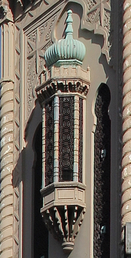
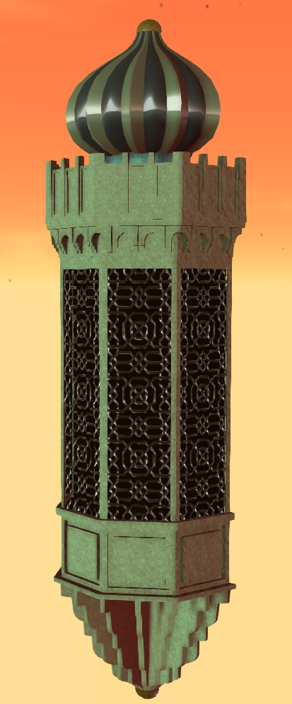
He desired an arabesque bay window, modelled after a theatre in Melbourne.

"No problem", I said. "what does it look like"

The photo shows the real life bay window. The onion dome on the top is reminiscent of the onion domes that I used in Aurora - my 2014 build for Fantasy Faire no doubt one reason why the job came my way.

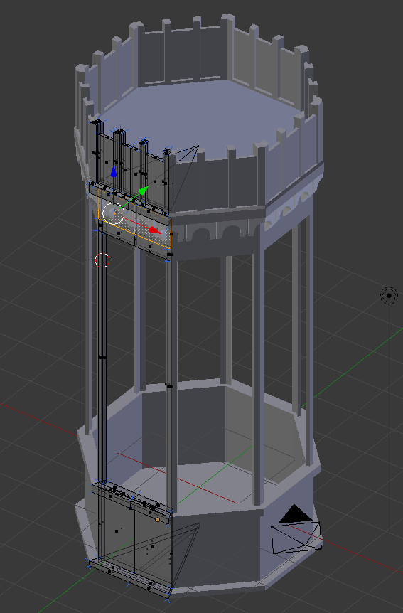
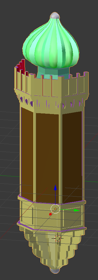
I often start a build in Mesh Studio but as I have been putting effort into my new workflow tools lately I decided to make this from scratch in Blender, so I set to work making an octagonal frame that I'd halve later.

I had of course forgotten two very important questions. "How big is it and how many LI do I have to play with?"

The answer came back the next day, it would need to be 9.5m high, 2m wide and about 1.5m deep,

"OK, that seems reasonable, what about the land impact budget..."

"About 2LI?"

Much teeth-sucking followed, 2LI for a large object with high detail was not an easy task.

"ookkkay." I said not wishing to give up without at least trying.

You may recall from previous blogs that the LI calculation is impacted by the scale, moreover, the issue is compounded by the realistic distance that an object will be seen from, and by whom.

If you are making a desk lamp, that will only ever be seen within your tiny office, and only ever seen by yourself, then you can take all manner of shortcuts that ignore the lower LODs and assume that the viewer has adjusted their viewer LOD multiplier etc.

In this case, though, we have a perfect storm of LOD and LI demands.
  1. Reasonably large in scale
  2. Visible from a distance as it is an external component.
  3. Seen by any visitors to the sim whose viewer settings cannot be "presumed"
  4. It needs to be low LI.
Large size means that the triangle rich HIGH LOD will be visible for a larger distance and this will put up the cost. The biggest cost is, however, going to be the MED LOD which will be visible across a very large part of the region, and thus is going to need to look pretty good.

Advice for the faint hearted

The following section *is* very long winded. It is about driving down the LI from an initial 15+ LI trial upload to the low target of just 2LI. I'll show you the working and comparisons but..

You don't need to do this to achieve results.
I find measurement is the best way to track your progress but that's just me. You can of course try these things on your objects and see how you get on without needing to measure every deatil.


Thinking about budget.

Let's do some quick maths then....no let's not, I wrote an AddOn for this...

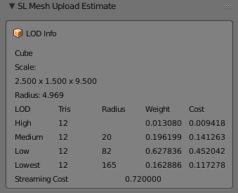
Using a Cube of the right dimensions we find the following information

A radius of almost 5m means that our HIGH LOD model will be visible to the default user setup within 20m. Now given that this is nearly 10m high and will sit on the side of a hotel, we can assume that many users will be seeing it from further than 20m away. So as we suspected the MED LOD needs to look good. What's more, the LOW LOD will kick in at 82m. Now this is New Babbage, visibility of 82m is unheard of but we can expect people to want a viable silhouette, so we'll have to make some effort on the LOW LOD too.

We know that my plugin values for the cost are over estimating but the proportions are probably not far off. Triangles in the MEDIUM are going to cost about 15 times that of the HIGH, with the LOW costing 3 times that of the MEDIUM

In fact, we can check this using an inworld analysis script.

Radius    Total LI  HIGH LOD   MED LOD    LOW LOD    LOWEST LOD
4.968652  0.729080  0.154618   0.348042   0.216630   0.009789
LOD sizes in tris :      197         30          6          1
LOD sizes in bytes:     3536        857        476        400
Cost per tri(LI)  : 0.000785   0.011773   0.037674   0.009767

We see that the ratio between LODs at that scale is:
HIGH/MED    15:1
MED/LOW      3:1

We can also see that our budget of 2LI is going to be tough.
SL rounds down so we can creep up to 2.5.
2.5LI is 3571 triangles in HIGH LOD.
For every triangle we put in the MEDIUM LOD we must sacrifice 15 in the HIGH
For every triangle in the LOW LOD we must sacrifice 45 in the HIGH

What is more, we are working on a symmetrical Mesh, every triangle we place on one wall becomes 4 in the final mesh so our full budget per wall is 892.

Making a start

I'd started with an octagon using 3 mirror modifiers to take a single face and reflect it up into 8. The idea would be to make the octagon then slice it in two. Very quickly I realised this was the wrong path (slicing a mesh in half is always best avoided) and instead switched to using array modifiers.

The model is built to be relatively efficient. All normal first stage optimisations have been made. The two most common for me are:-

  1. Remove hidden faces.
    This applies to any mesh creating workflow, when you work in Mesh Studio you do this before creating the Mesh by setting the face to be transparent. With Blender, a similar process can be applied. MY method is to create a "fake" material face could DELETEME, assigning any that faces that I find which cannot be seen as I go, deleting them later in the workflow.
  2. Remove duplicate vertices
    As you work you often end up with overlapping mesh and blender has a convenient function to remove duplicates. It has a slider to control the threshold (how near they must be) which is great for tidying up messy joints, but it needs to be applied with care or you'll lose small details by mistake. This is also a job that can take place numerous times in a workflow. For Example, if you apply modifiers, especially mirror or array modifiers, you may get duplicates left. 

I modelled the main body, the crenellations, the dome and the lower corbel separately merging them into the joined model. The result was as follows:-


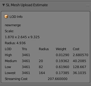
3461 Tris in my HIGH LOD Mode and coming in at around 3LI, now with the error in my AddOn we can suspect that this would be about 30% less. so perhaps 2LI, which will leave us nothing at all for the MED LOD. We are going to need to do some serious work to hit our target and frankly, I don't want to lose any of the detail I have if it can be helped.

Breaking it up - Bespoke optimisation

So what can we do? We've already done the basic stuff. We have a clean looking mesh, we removed all the doubles. So we now need to look at item specific tactics, is there anything about this object that we can use to our advantage?

If we look at the object we notice a number of things. The main body is quite plain. I modelled the fretwork for the window but only used it to generate the textures and bump maps, apart from that it is really just a few inset panels. The crenellations are far more detailed with a curved and stepped arch. Then we have the dome, At first, I reused the old Aurora dome but quickly decided to recreate it from the start, either way, it has to have smooth curves and they are costly. At the bottom end we have the curved corbel another comparatively costly piece.

By linking all of these into one we are paying the price of a 5m radius object when by separating them out we van get those same triangles cheaper. Will it make a major saving?
Let's have a look.
LOD
HIGH tris
Radius
Cost
Notes
Combined
3461
4.94
2.680
All 4 parts joined and dupes removed
Dome
787
1.58
0.062

Crenellations
1650
1.77
0.164

Bay Window
276
2.82
0.069

Corbel
784
1.65
0.067

Separates Total
3497

0.362
Notice the slightly higher tri count.

So why would we ever join the mesh? The combined mesh has a couple of things in its favour.
Feature
Joined
Separate
Server Cost
Always 0.5
0.5 for each unit. In our case 0.5 x 4 gives us 2LI Inside out target so perfectly acceptable.
Texturing
Eight texture faces
Eight faces per unit. A lot more work perhaps. Also a lot more flexibility
Upload cost
Not really sure this matters
What's a few Lindens between friends?
LOD switch
A biggy. The LOD will switch based on the BB of the single unit
The LOD will switch independently for each item. This is good and bad. It can mean that the larger features stay as HIGH for longer than the small features. All the more reason to design good quality LOD models
LOD calculation
The crux of this issue. All triangles are going to be costed at the size of the overall object. Imagine a full-scale house with a mesh door knocker.
With the parts separated into sensible chunks we pay a more appropriate price and can choose where to place out details. This has worked incredibly well on our broken up window the High LOD coming in at about 13% of the merged

So what have we achieved, so far?

We had a hard target to hit at 2LI for a large and potentially fiddly mesh. My first "sketch" was coming in at 15LI with no other LODs and that seemed to suggest a big problem ahead. But by the time we've sanitised the Mesh to just what we needed and nothing more we were down to the low single digits. 

We then made use of the fact that this object has some large flat expanses that unhelpfully push up the scale. Breaking that down we have now reduced out HIGH LOD exposure to less that half an LI. Leaving us up to 2LI (remember LI gets rounded to the nearest whole so we can go to 2.5) for the remaining LODs. 

The bad news is that because we have broken this into smaller parts we now need to consider that the LOW LOD might be seen from nearer than before and a larger budget might be needed there.

Coming soon...

Next up we will look at the MED LOD model and see how we can keep our design goals and our LI budget aligned.