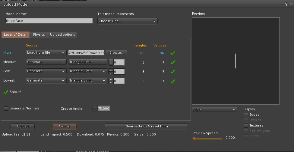
Showing posts with label bug. Show all posts

Friday, 28 July 2017

A (con)Vexing problem - Fixing doors becomes a little easier.

Anyone who has been around Mesh building groups for any amount of time will be familiar with the anguished cries of "Why won't my door work?". One of the most annoying aspects of trouble shooting that problem is about to become a thing of the past.

I covered the "door no working" topic in this blog post last year. Those of us who advise/mentor know what to check for. The first thing is to make sure that they uploaded a physics shape. "Have you switched the physics shape to Prim?", they will typically do this and mostly it fixes things, but then there is still a reasonably significant proportion who return to say "I've done that and it's still not working."

The next step, typically, is to ask what the dimensions of the mesh are. Quite often the poor beleaguered builder will look quizzically at you, conclude you are mad and perhaps go off on some crackpot detour led astray by another helpful but ill-informed soul, they will often end up dropping into physics view and concluding that they are right and that the blocked door is a bug. They are half right, there is a bug, but it is not in the "blocked door".

Who debugs the debugger?

How to find physics view in Firestorm (shoudl work on most viewers)
When we are looking for issues with physics that go beyond the basic checks it is often the case that those who are at least aware of the advanced menus will take a look at the Render Metadata menu, and the Physics shapes view in particular.

Physics shape view is a special display that encodes a lot of information about the physics in the scene. You can use this to examine the physical representation of the region and in particular of the object that you are interested in.However, herein lies the issue. There is a bug, it has been around for a number of years and many of us have raised Jira bug reports against it in the past. With my more recent switch to become a developer on the Firestorm viewer, I was able to spend some time to work out why there was a bug here and what the underlying issue was. You can read the Jira BUG report I raised for the technical background. 

The case of the invisible wall

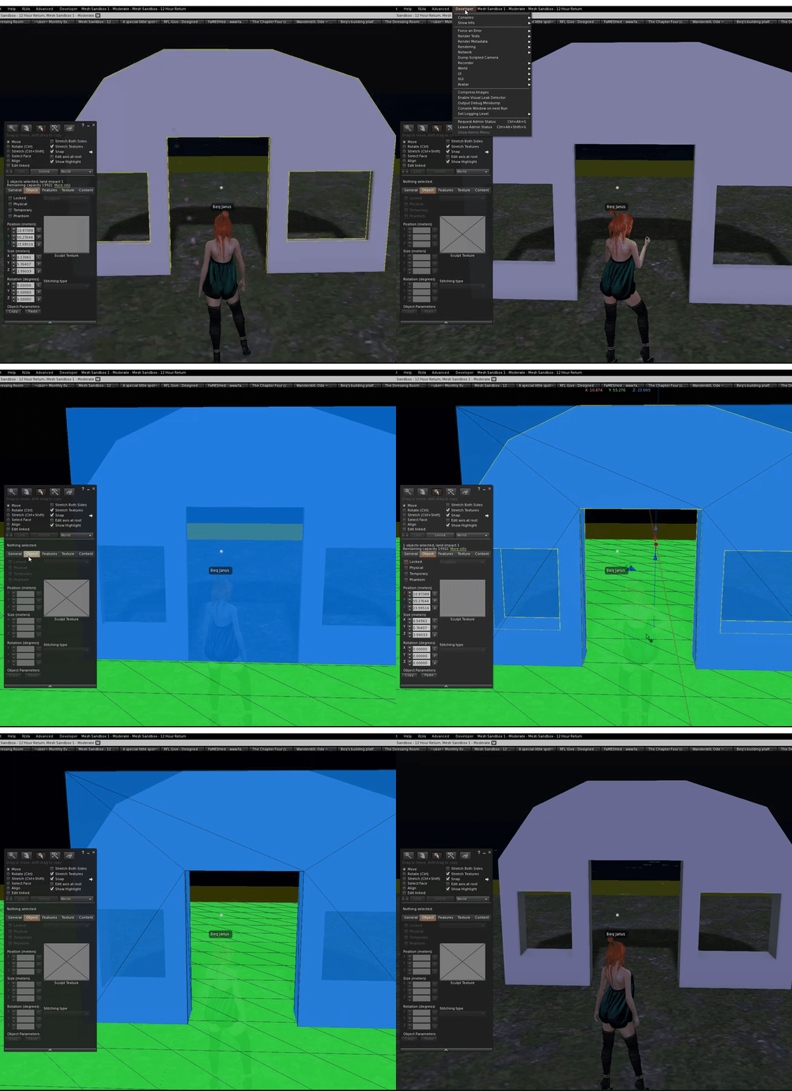
A typical example, perhaps the most typical example, is a creator who has uploaded a mesh wall with a door in it. The creator sets a custom physics shape in the uploader and remembers to set the phsyics type to "Prim" yet still the doorway refuses to let her pass. She concludes that she must have uploaded it badly and looks at the physics representation using physics shape view. 

This is what she sees.


"What the heck? The physics shape looks perfect why won't it let me through?"
The problem is that the viewer is lying to us. What it thinks the physics should look like is not in agreement with what the server is enforcing.

So what is going on and why is the viewer lying?

Size Matters (sometimes)

If you've read my previous blogs you'll know that there are two distinct ways of representing a physics shape (or physics volume to use a more correct term), hulls and triangles. The key difference is that a triangular physics shape (mesh) changes its value based upon the scale, and to make matters more confusing, it changes inversely with the object scale. this is counter intuitive to the uninformed.

Why does physics cost grow as the objects get smaller?

When you upload a mesh you can define the physics shape that will be applied to the object.
The default gives you no user defined physics at all, in this situation all that the object has when rezzed in world is the "convex hull" and "none" option. We are not going to concern ourselves with this today.

If you look at the physics tab of the upload dialogue you find a selector that allows you to choose a mesh model to be used for your physics.
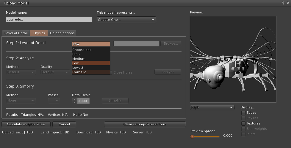
This is a very important step and often overlooked by Mesh creators.
The Mesh I am using in the example here is one of my bugs from this year's Fantasy Faire. It has around 20000 triangles in the form shown (High LOD) and was designed to be very large (40m wingspan). It would undoubtedly be an awful choice for the physics shape. One of the basic rules of physics uploads is to keep things very simple, the reason is plain; if you want to reduce the lag on the sim and in your client then minimising the work that has to be down to determine when someone has collided with your object is essential.

So how does a collision get detected?

Whenever another object comes within the radius of my object then SL has to decide whether a collision has occurred, this also applies for rezzing and sitting on objects.
If I were to use the High LOD model as my physics shape then every one of those 20000+ triangles is potentially intersecting with a part of the other object. Special optimisations segment the space between objects to reduce the number of checks that need to be made but in the end, it resolves down to individual triangles. the smaller the triangles the more work has to be done to determine which, if any, it will intersect with and the higher the overhead on collision detection.

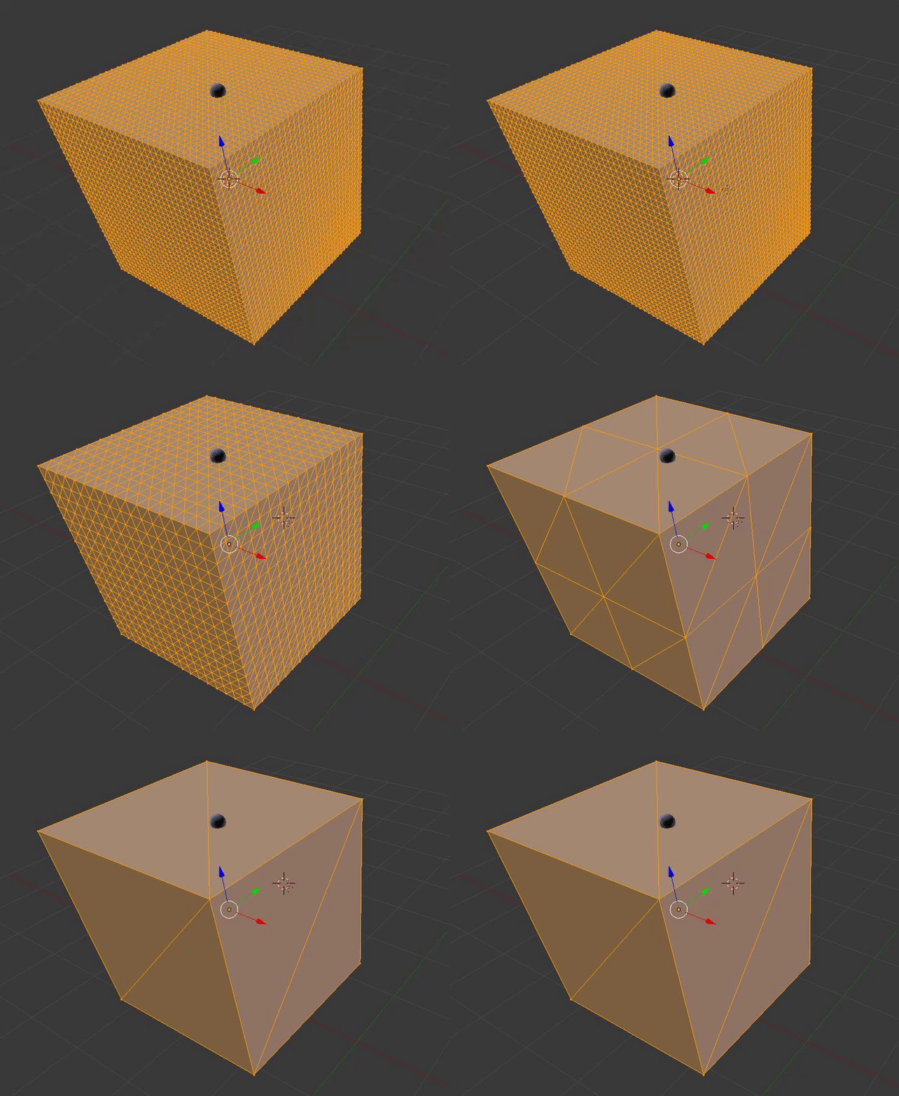
In the following animation ask yourself "Which of the triangles is the ball touching?"

Which Triangles is the ball touching?


In order to encourage well-constructed Mesh assets, the Second Life land impact algorithm includes a physics weight component. The algorithm itself is not fully public and the documentation incomplete and inaccurate but the principle is clear. The more "skinny" triangles in the object the more your physics cost will penalise you.

The obvious side-effect here is that as you make an object thinner in one dimension the triangles will become thinner and as such will increase the physics cost. The smaller it gets the higher the physics cost. In theory, as width tends to zero the physics cost tends to infinity. This is where Second Life steps in and takes control. In order to prevent the physics cost from going asymptotic Second Life has code that forces an object to have the physics of a simple box once its dimensions go below a certain limit and as many of you will have known from the outset, that is exactly what was affecting our little mesh door. The rule that the viewer enforces is as follows:-

IF object has more than 2 dimensions less than 0.2m
THEN force the shape to a convex box.

"Wait a minute, that's not right" I hear you cry, and yes you are right, our wall was more than 0.2m in all three dimensions. That's because the viewer does not actually enforce the phsyics. The server does and physics view, simply draws what the viewer "thinks" the phsyics is. But it is wrong.

The rule that the server enforces is different.

IF object is a prim AND has more than 2 dimensions less than 0.2m
THEN force the shape to a convex box.
ELSIF object is a mesh AND has one dimension less than 0.5m
THEN force the shape to a convex box  

so here is our answer, the server is far less tolerant of thin meshes than the viewer thinks causing the viewer to display the normal mesh shape when the server has already given up.
Making things right, or "you cannae change the laws of physics, captain"

The big question though is, which one is more correct?
The simple answer is the server rules are right because those are the ones that are enforced, but the 0.5m limit on walls is a pain in the rear, nobody wants thick walls and while analysed mesh is a solution, very few know about this and the second life wiki still recommends non-analysed!
For this reason, I have been lobbying for solution 2 on my Jira to be considered. Fingers crossed we may get the ability to make thinner Mesh walls.

In the meantime, I have updated Firestorm to correctly reflect the enforced laws of physics. This should greatly improve the use of the physics view as a debugging tool.

The following video shows the new changes in operation and now a blocked door looks blocked until the dimensions change. It should be in the next release of Firestorm.


Another overly long and exhaustively explanatory blog. I hope it explained a few aspects of physics and one of the (soon to be ex) annoyances.

Love

Beq
x


Sunday, 9 October 2016

Not as simple as it looks...

A little bad news

In my last post on "bug hunting", I talked about the LOD decay issue and a potential fix. I said in the blog that "subject to QA" it would be coming to you soon and sure enough QA found an issue. It turns out, rather a large issue given that as a result of my fix a lot of mesh textures get utterly corrupted. Needless to say, that patch was backed out. Thanks to Ansariel Hillier and Whirly Fizzle from the Firestorm development team for spotting and doing some initial troubleshooting of it for me while I was overseas.

It is not all bad news

The good news is that I have submitted a new patch that uses a completely different method. It is a method that I shied away from first time as I felt it was too close to the critical path, i.e. a part of the code that has significant impact on the overall performance, and chose to make changes far earlier. I am happier with the new solution, it is simpler, more elegant in some ways, and overall improves the performance ever so slightly by avoiding some convoluted checks when calculating the LOD for Mesh.

This patch has also highlighted the rather bizarre dependency that a mesh has on the legacy prim definitions and adds weight to my request for documentation on why this is done. Once I have cleared a few other loose ends up I may well circle round and have a look at this again.

On a related note. Complexity and confusion

With the recent introduction of complexity limits to the viewer has confused some people and highlighted certain bad practices in Mesh creation. However, due to a range of different "features" it is still not really as reliable as anyone would hope. Part of this is down to the fact the rigged mesh does not have its LOD calculated in the same way. 

In fact, for worn, rigged mesh the LOD is not based upon the radius of the object but is instead tied to the bounding box of the avatar that wears it. This is a quite deliberate choice, explicitly mentioned in the viewer code,  and means that if you wear a Mesh body and Mesh head and Mesh hands, that they ultimately LOD swap at the same time, rather than the hands decaying first (being the smallest) then the head and later the body but it also means that the complexity calculations need to consider this (which they do not at present). This means that those super high poly onion skin mesh head that melt down your graphics card in a busy sim, are only getting a complexity score based on the apparent scale and yet they are visible based on a much larger scale. Once you realise this...you can then read my Jira here because it is actually worse than that, rigged meshes are being given a far far easier ride that they deserve.

All this being said, it is what it is and changing this stuff is hard because it breaks things. So the Lab are looking at pulling together all the oddities in the LOD and complexity calculations and reviewing them to see what if anything can be done to make the complexity numbers more meaningful and usable. There is no timescale for this, just an intention to review things at the moment. I for one will be keeping a keen eye on progress.

Love 

Beq
x

Saturday, 1 October 2016

Bug hunting - Fixing an ancient LOD issue

Those of you who may have read my blog post in July, "Tell your friends - An old bug that people really ought to know about." might be interested to know that I have made a lot of progress towards fixing it.

TL;DR

The long-standing bug discussed in the blog (see link above) that impacts the way that certain Mesh objects decay their LODs has been identified and fixed. I will be submitting the patch to Firestorm and other TPVs where applicable and back to the Lab so that (if it is accepted) we can be rid of this pain in the posterior.

Introduction

After having suffered and grumbled at this bug for a long time I decided to bite the bullet and for the first time since about 2009, build and debug the viewer. After a week or so of digging around and working out how V3 viewers hang together, I now have a solution to the problem we observe, but it still needs to go through QA and of course the thing I cannot know...why did it do that? More of that later...

The basic problem

Here is the basic problem as we originally observed it.

Any mesh object with either 3 or 4 texture faces will crumple earlier than an identically sized mesh with only 2 texture faces.

But in fact it is worse than that (a little).

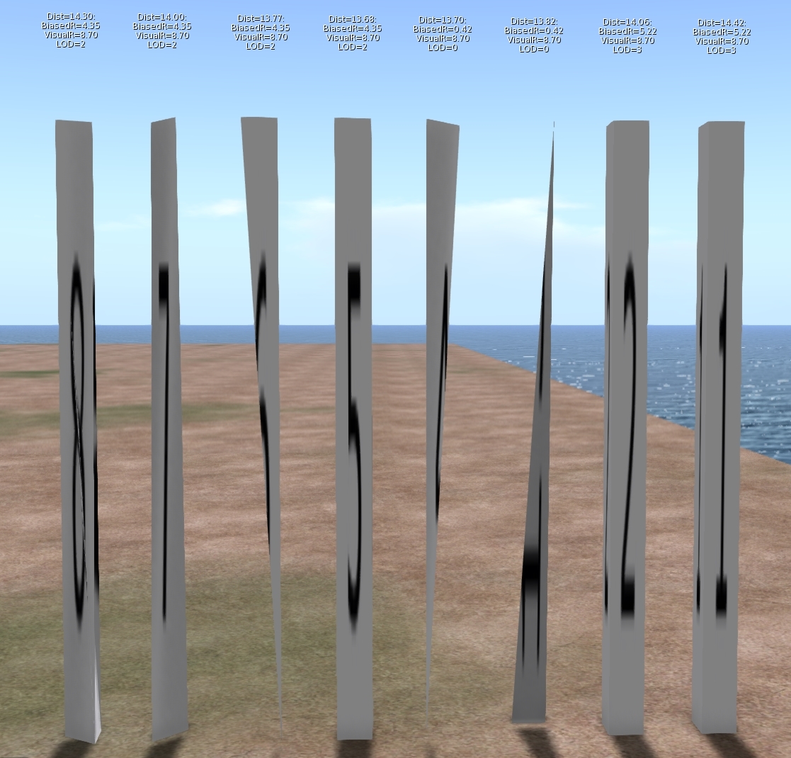
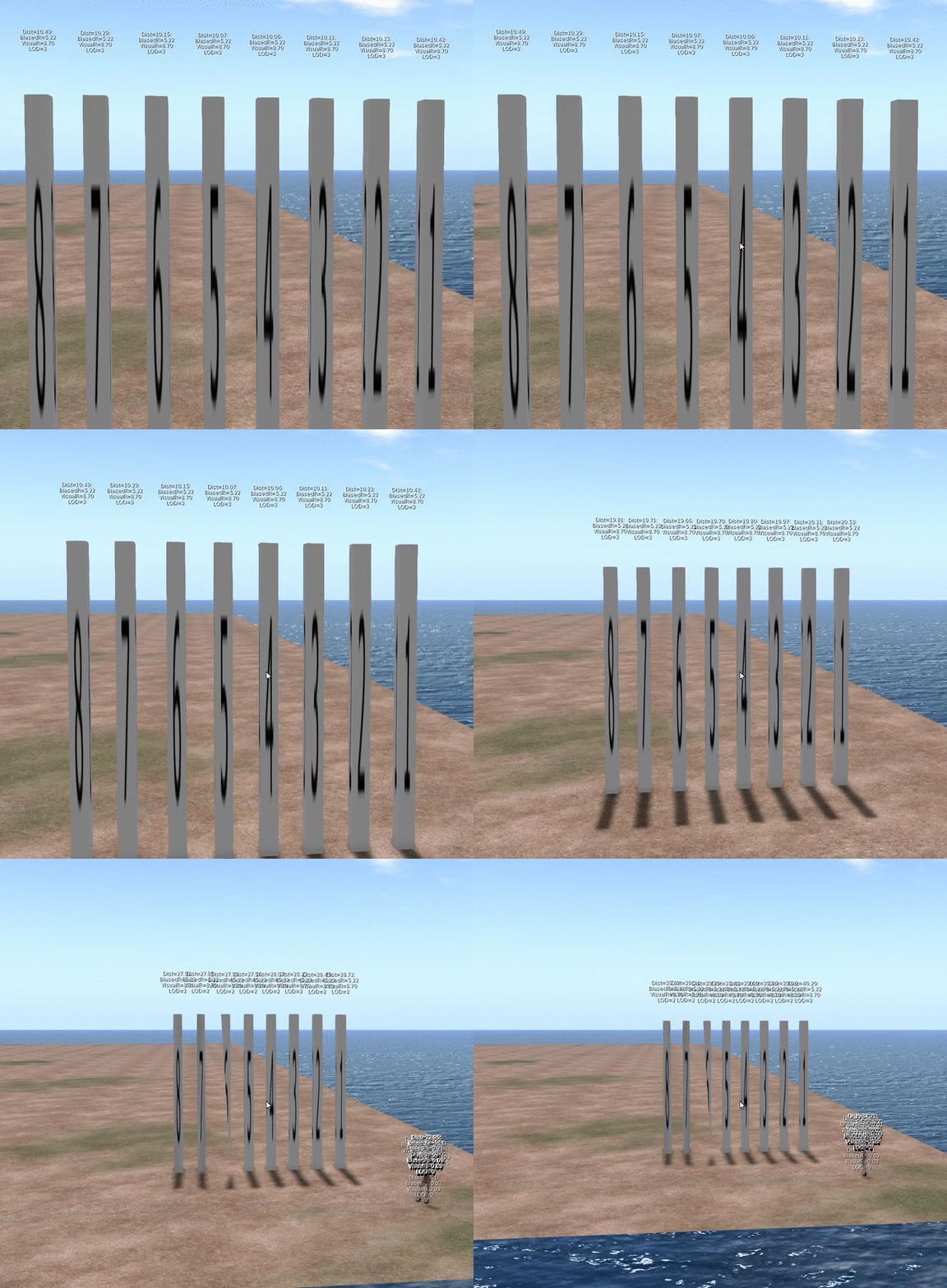
As I dug into this problem it turns out that this is not a problem that affects 3 and 4 materials only, it just affects them worse. Meshes with 5, 6, 7 & 8 material faces will also collapse earlier than the comparable 1 and 2 material versions. The following image will illustrate

The image shows 8 identically sized columns. Under normal circumstances, one would expect these to look identical and change LOD at the same distance from the viewer. The textual display above each shows the following:
Dist:                   The distance of the object from the viewer.
Biased Radius:   An adjusted radius based upon a biasing algorithm, the source of our woes.
Visual Radius:    The "True" Radius defined by the bounding box of the object.
LOD:                  The Level Of Detail currently shown. 3=HIGH, 2=MED, 1=LOW, 0=LOWEST

The display is a bug fix/enhancement of my own and if accepted will appear in a future viewer. It is a change to the existing Render Metadata -> LOD Info which is basically broken on all existing viewers. I should also note that I use the term radius here, because not only is it the term we use inworld when examining the LOD equations, but it is also used in the code, all of which is despite the fact that it is not the radius at all but the long diagonal of the bounding box!

As you can see, Objects 1 & 2 are still at LOD 3, even though their distance from the camera is marginally more than the others. Further scrutiny of the hovering figures shows that the Biased Radius is 5.22 compared to 4.35and 0.42. Objects 3 & 4 have collapsed to LOD 0, with a biased Radius of just 0.42 they had little hope of remaining visible. While all the others have decayed to a slightly withered LOD2.

But why does this happen? To understand this we need a little implementation detail.

What does a mesh look like on the inside?

SL is often criticised and even rubbished for the way it does things, but if I am really honest I have a great deal of admiration for the general architecture. For a system design 15 years ago it has managed to grow and adapt and shown remarkable durability. The code certainly bears many battle scars and the stretch marks of its adolescence glare an angry red under scrutiny but the fact that it has gone from super optimised prims through to industry standard Mesh, growing as and when the technology of its users was best able to adopt it is very impressive. 

Second Life has achieved this longevity through a series of "cunning plans" which have extended the capability without altering the infrastructure drastically. all the objects in your inventory have a top level structure which is basically a legacy prim, extensions have been variously grafted on to this but leave behind the traits of the original prims. This means that, even though they are unused, a mesh has a slice, taper and cut setting as well as many others.

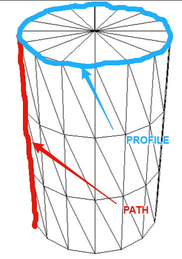
These top level prims also denote what type of prim they are, cube, sphere, cone, etc. and Meshes are no different. The basic shape is determined through two parameters the PATH and the PROFILE. Thus a sphere has a PATH and PROFILE of CIRCLE, while a cylinder has a PATH of LINE and a PROFILE of CIRCLE. Sculpts came along later and are indicated by the presence of a sculpt parameter block on the end of the Prim. Perhaps surprisingly Mesh is denoted as a type of Sculpt with the "SculptType" is set to the value 5 representing Mesh.

This allows the "cunning plan" that the settings for a sculpt can be reused. In a traditional sculpted prim, the SculptID holds the asset server UUID of an image that defines the sculptmap. In a Mesh the same field is used to hold a UUID of the underlying Mesh. It is important to note here that the Mesh that you upload is given this UUID that is the "child" of the Mesh object. You never actually get to see or know the underlying Mesh asset ID inworld.

So we now know that a Mesh is really a legacy prim, denoted as a sculpt, whose map is redirected to a Mesh defintion. So let's see where it goes wrong.

LODScaleBias and the legacy impact.

My first task in trying to fix this bug was to start to map out the viewer. It has been at least 6 years since I last looked at the viewer code and back then I was only really building it for my own purposes. The code has all the hallmarks of mature and much patched and extended code and is a bit of a rat's nest at times, but nestled deep inside the nest is a function simply called calcLod()
This function, along with the name, also was home to the output for the Render Metadata->LOD Info function.

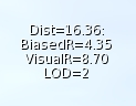
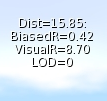
The Render Metadata services are a set of great tools for builders and developers who are trying to understand a problem, those who have read this blog in the past will be well aware of the physics display. The LOD Info display has been a bugbear of mine for some time, I have never been able to work out what it was displaying, It would show a number that would typically not change with the LOD display and was to all intents and purposes useless. It turns out that is exactly what it is. At some point in the past it appears to have been borrowed for some other purpose and upon examination had nothing to do with the LOD at all. The damning evidence was a commented out remnant of the original call. My first "fix" of the expedition was, therefore, to make this function more useful, the new display is shown on the left. I will be submitting that patch separately.

Back to our friend calcLOD().
I won't post the code here, it is too long but the function does what you would expect it to do given its name but the devil is in the detail.

BOOL LLVOVolume::calcLOD()
{
F32 radius;
F32 distance;

if (mDrawable->isState(LLDrawable::RIGGED))
{
// if this is rigged set the radius to that of the avatar              
}
else
{
distance = mDrawable->mDistanceWRTCamera;
radius = getVolume() ? getVolume()->mLODScaleBias.scaledVec(getScale()).length() : getScale().length();
}
.....etc etc
}

There are a couple of interesting diversions in this function, the first we covered above, the second is a special clause for rigged attachments which deliberately adjusts their LOD scale to be that of the avatar that is wearing them. This is the subject of a Jira and is likely to come under scrutiny in the current quest to improve complexity determination.

However it is the code in bold and further highlighted that we care about. What is this LODScaleBias? Our amended LODInfo display proves that this is the culprit. The BiasedRadius of a 3 face Mesh is shown on the left and can be compared to the same mesh with 6 material faces shown in the example above. 0.42 when the true radius is 8.7, no wonder the thing crumbles. 

Digging deeper we can identify where the LODScaleBias vector is initialised. 
BOOL LLVolume::generate(){
...snip...
    mLODScaleBias.setVec(0.5f, 0.5f, 0.5f);
...snip...        
    if (path_type == LL_PCODE_PATH_LINE && profile_type == LL_PCODE_PROFILE_CIRCLE)
    { //cylinders don't care about Z-Axis
        mLODScaleBias.setVec(0.6f, 0.6f, 0.0f);
    }
    else if (path_type == LL_PCODE_PATH_CIRCLE) 
    {    
        mLODScaleBias.setVec(0.6f, 0.6f, 0.6f);
    }

 ...
So here we have it.

"Cylinders don't care about Z-Axis"

The code above sets up the bias. The default bias is <0.5, 0.5, 0.5> and I'm feeling rather stupid now because having said previously that Radius is not really the radius...if you take the long diagonal and half it then of course you do have the radius (the radius of a sphere that encloses the bounding box, at least.) We then get to the code in bold red. Here we find that if the legacy prim has a linear path and a circular profile then it must be a cylinder, 
The image to the left shows my hand drawn annotation of what those two parameters mean. Anyone who worked with prims will most likely understand the terms.

This does pose a couple of questions, the most obvious of which is:-
"Cylinders don't care about Z-Axis" WHY!!!!?

There seems no logic to explain why a cylinder would be set to LOD quicker. Clearly, when used as a column it results in a high number of long thin triangles but does that really warrant such punishment? I have enquired with a couple of Lindens to see if we can get some clarification on the history of this.

Noting the <0.6, 0.6, 0.0> when applied to our example mesh columns give a Radius of 0.42 we can confirm that this is , as had been suspected, how out poor Meshes are being evaluated, and so the second most obvious question is:-
Why is my Mesh arbitrarily being branded as a cylinder? 
Again there seems no rhyme nor reason to the 3 and 4 material face meshes being treated this way. If the lab responds with an answer to either of these I will post a blog to share the info.

Having determined why we have this issue we need to go and find out where. At first, this seemed a daunting task. Somewhere in all the viewer code was a single line or two that was initialising these parameters incorrectly. I decided to start at the very beginning. The beginning for any asset is when it gets sent from the server to the client, a little hunting and we find a function that is called to process and unpack an update message for an object. In this code, I found the point at which the parameters are unpacked and placed some additional logging to print out the settings. 

Lo and behold the viewer is not to blame at all. The Object is already tainted before it arrives. This means that something is happening on the server and it would seem to be deliberate. 

How can we assume it is on the server? 

We have in previous blogs examined the Mesh Asset upload format and can note that there is no room in there for the legacy parameters. Moreover, that asset is the data that is referenced as the "SculptId". The Containing/parent prim is different, it is created on the server side, presumably during the validation of the upload process, the initilisation of the parent object must be assigning default values based on certain consistent criteria and as such results in the problem. As with the above, I have asked the lab whether they can confirm the reason for this, primarily so that we can understand if there are any side effects.

Having noted that Meshes are already tainted I added code to list out the types of Mesh and using a conveniently empty sim on the beta grid Aditi I created my series of 8 "identical" meshes.
the result can be summarised as follows.

# faces
PATH
PROFILE
BIAS
1
CIRCLE
CIRCLE_HALF
<0.6,0.6,0.6>
2
CIRCLE
CIRCLE
<0.6,0.6,0.6>
3
LINE
CIRCLE
<0.6,0.6,0.0>
4
LINE
CIRCLE
<0.6,0.6,0.0>
5
LINE
EQUALTRI
<0.5,0.5,0.5>
6
LINE
SQUARE
<0.5,0.5,0.5>
7
LINE
SQUARE
<0.5,0.5,0.5>
8
LINE
SQUARE
<0.5,0.5,0.5>

That is the end really. With the fix in place the Meshes quickly resolve and the new LOD Info display confirms that the Bias is no longer unfairly having some meshes. As for side-effects, we only modify at run time, and nothing is ever saved back to the server. Moreover I have implemented this to be configurable and should any issues arise it could be easily disabled. 

So what next? 

I am no cleaning up the code to remove or at lesat comment out any of the debug logging I used. I will then create a submit a patch to Firestorm. Having spoken to Oz Linden, I have been asked to sign a contribution agreement, this is a form that protects the Lab (and thus all of us) from me giving code and then claiming some licensing later.Once I have that in place the lab can accept my change and would then consider it. So that means that subject to QA and testing to follow hopefully we can put this bug to rest once and for all. 

It leaves a few loose ends. 

Why does a Cylinder ignore the Z? I just want to know.
Why does the server do this and will/should the server-side get fixed?
Would fixing this on the server make a difference to the SL Map

That's all for now, I shall leave you with an animation of the FIX in action,

Love

Beq
x

Thursday, 7 July 2016

The truth about mesh streaming

The truth about mesh streaming

Ever wondered why a mesh with the same number of triangles could give different LI? Or how the impact of each LOD model is assessed? Stick with me today and hopefully, I'll show you.

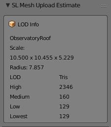
Today's post is the fifth in the series of meanderings through Blender Addons. Yesterday, we left things in an OK state. My AddOn is reflecting the correct triangle counts for the models (and correctly associating the models with the LOD they represent).

Today we will look at the Mesh Streaming Cost algorithm and have a go at converting that to python.
This is an unashamedly technical blog. I will try to explain some aspects as I go through but the nature of the topic demands some technical detail, quite a lot of it.

I am going to work from the latest Firestorm Viewer source, and a couple of somewhat outdated wiki resources. The wiki resources themselves should be good enough, but the problem with them is that you can never be sure if things have been tweaked since. Ultimately though we have a real world comparison, our estimates should match (or be close to) the Viewer upload, we will test this at the very end.

A good place to start is the Mesh Streaming Cost wiki page as with many wiki documents it is out of date and not entirely correct. However, we can use it as a starting place. The concept section explains the thought behind this. The equation part is where we will start.
  1. Compute the distance at which each LOD is displayed
  2. Compute the area in which each LOD is relevant
  3. Adjust for missiing LODs
  4. Scale relative weights of each LOD based on what percentage of the region each LOD covers.
  5. Compute cost based on relevant range and bytes in LOD
It goes on to tell us what the LOD transition distances are, details we covered in the post yesterday.

Using these we can write another helper function
def getLODRadii(object):
    max_distance = 512.0
    radius = get_radius_of_object(object)
    dlowest = min(radius / 0.03, max_distance)
    dlow = min(radius / 0.06, max_distance)
    dmid = min(radius / 0.24, max_distance)
    return (radius, dmid, dlow, dlowest)

This function takes an object and using our previously written radius function and applying the knowledge above, returns a list of values. The radius itself, the High to Mid transition distance, The Mid to low transition and finally the Low to Lowest.

We use a constant max distance of 512 as it matches that used in the code example and the current live code. Quite why it should be 512 (2 regions) is unclear to me.

So now we should be able to add a new column to our display and show the LOD change radii

Step 2 is to compute the area for each LOD. Now that we have the Radius that is a simple task.

def area_of_circle(r):
    return math.pi * r * r

The function above returns the area for a given radius.

The next step is "Adjusting for missing LODs", we'll take this into account when we display things. But in terms of the algorithm, if a given LOD is missing then the next highest available LOD is used.

We can now progress to the "Computing Cost" section. This section gives use the following formula.

    Streaming Cost =
        (   (lowest_area / total_area) * bytes_in_lowest
          + (low_area    / total_area) * bytes_in_low
          + (mid_area    / total_area) * bytes_in_mid
          + (high_area   / total_area) * bytes_in_high   ) * cost_scalar
The first part is a ratio, a weighting applied to the LOD based upon the visibility radii.
The second part is more confusing on its own, "bytes_in_LOD" where did that come from?

The answer lies in the note just below the pseudo code.
In the details of the implementation, the cost_scalar is based on a target triangle budget, and efforts are made to convert bytes_in_foo to an estimated triangle count.
So what does that mean exactly? The answer lies in the C++ code below it and, in particular:
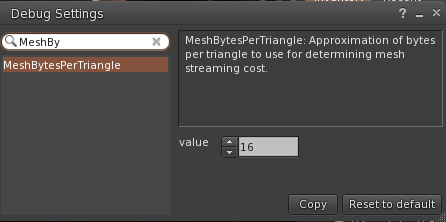
F32 bytes_per_triangle = (F32) gSavedSettings.getU32("MeshBytesPerTriangle");
This is a setting stored in the viewer that approximates how many bytes are in a triangle for the purpose of converting "bytes" to triangles. Looking at the current live viewers, we find that the setting has a value of 16.

This value is then used to convert a bytes_LOD value to a triangles_LOD value.
    F32 triangles_high   = llmax((F32) bytes_high-METADATA_DISCOUNT, MINIMUM_SIZE
                            /bytes_per_triangle;
This deducts a METADATA_DISCOUNT constant to remove the "overhead" in each mesh LOD to leave only the real triangle data. The remaining bytes are divided by our bytes_per_triangle to get the number of triangles. This raises the question of whether 16 is the right "estimate" Indeed, why is it an estimate at all? In Blender we won't be estimating, we know how many triangles we have. However, it will turn out that the page is missing one vital piece of information that explains all of this...However, we will come back to this once we have worked out the rest.

Looking in more detail at the implementation we find that lowest area and the related "areas" are not quite what they seem.
In the C++ implementation, we observe that high_area is indeed the area of the circle defined by the roll off point from High to Medium LOD,
F32 high_area   = llmin(F_PI*dmid*dmid, max_area);
but we discover that mid_area is the area of the medium range only, excluding the high_area. The area of the Ring in which the Medium LOD is visible.The same applies to the others.

Putting this all together in python we get the following:-

def getWeights(object):
    (radius, LODSwitchMed, LODSwitchLow, LODSwitchLowest) = getLODRadii(object)

    MaxArea = bpy.context.scene.sl_lod.MaxArea
    MinArea = bpy.context.scene.sl_lod.MinArea

    highArea = clamp(area_of_circle(LODSwitchMed), MinArea, MaxArea)
    midArea = clamp(area_of_circle(LODSwitchLow), MinArea, MaxArea)
    lowArea = clamp(area_of_circle(LODSwitchLowest), MinArea, MaxArea)
    lowestArea = MaxArea

    lowestArea -= lowArea
    lowArea -= midArea
    midArea -= highArea

    highArea = clamp(highArea, MinArea, MaxArea)
    midArea = clamp(midArea, MinArea, MaxArea)
    lowArea = clamp(lowArea, MinArea, MaxArea)
    lowestArea = clamp(lowestArea, MinArea, MaxArea)

    totalArea = highArea + midArea + lowArea + lowestArea

    highAreaRatio = highArea / totalArea
    midAreaRatio = midArea / totalArea
    lowAreaRatio = lowArea / totalArea
    lowestAreaRatio = lowestArea / totalArea
    return (highAreaRatio, midAreaRatio, lowAreaRatio, lowestAreaRatio)

This should give us the weighting of each LOD in the current models at the current scale. So let's add this to our display.

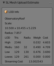
Here we can see that our Medium and Low LODs are carrying a lot of the LI impact and thus if we want to manage the LI we need to pay a lot of attention to these. The more observant will note that the Lowest is effectively 0, and yet we are telling it to use the LOD from the LOW, this makes no sense at first glance, it should be very expensive. The explanation is in the radius column. Lowest does not become active until 261m, which is outside of the 256m maximum  (see maxArea in the code above), this means that the Lowest is clamped to a radius of 256, which matches the radius of the Low and thus results in 0 weight.

With all this in place, we are finally able to have a first run at calculating the streaming cost.
Once again we refer to the C++ implementation for guidance.
    F32 weighted_avg = triangles_high*high_area +
                       triangles_mid*mid_area +
                       triangles_low*low_area +
                       triangles_lowest*lowest_area;
 
    return weighted_avg/gSavedSettings.getU32("MeshTriangleBudget")*15000.f;
 In our python translation this becomes:

        weightedAverage =   hi_tris*highAreaRatio + mid_tris*midAreaRatio + low_tris*lowAreaRatio + lowest_tris*lowestAreaRatio
        streamingCost = weightedAverage/context.scene.sl_lod.MeshTriangleBudget*15000

I am not a fan of the magic numbers used here (MeshTriangleBudget is in fact another viewer setting and has a value of 250000, the 15000 however is a simple hard coded constant so we have little choice but to replicate it.

For our final reveal for tonight then let's see how out LI calculation has performed.


Oh dear...
Well, I guess it had all been too easy so far.
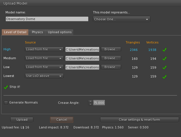
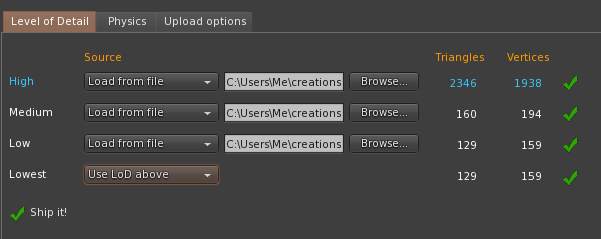
The Firestorm upload has calculated that this object will have a streaming impact of 8LI
Our determination has calculated 13LI. That is a considerable difference, what could possibly have gone wrong?

The answer was hinted at previously; it is to do with the estimate, the bytes_LOD values and what they actually are. The problem lies in the fact that your mesh is not sent back and forth unaltered from the DaE file that you upload. In fact, it is uploaded in an internal format that compresses each LOD model. The bytes_LOD values represent the compressed size of the actual mesh that will be streamed, the estimated bytes_per_triangle of 16 is, it would seem greatly underestimating the compression level.
In my next blog, I will examine the internal format in more detail. We'll explain why the estimated bytes per triangle is wrong, and we will start to work out how we can make this work.

Until then, thank you for reading this blog. Please share or +1 if you have found it useful, or if you think that your friends might.

Love
Beq
x

Wednesday, 6 July 2016

Mesh accounting mayhem

Mesh accounting - Download/streaming costs

This post is the 4th in this series of posts about Blender Addons for SecondLife creation, and we (finally) get to sink our pythonic fangs into something concrete.

Previously...

Post 1 - We started to put a simple addon together to generate five copies of a selected Mesh and rename them according to their intended use.
Post 2 - We took it a step further by allowing the user to select which LOD to use as the source and which targets to produce.
Post 3 - We wrapped up the process, connecting the execute method of the operator to the new structures maintained from the UI.

So what next?

Tonight we are going to try (or at least start) to replicate the streaming cost calculation of SL in Blender.

A quick recap

For those who have not looked lately and are perhaps a little rusty on Mesh accounting here is the summary.
Firstly, I will use the term Mesh primitive to denote a single mesh object that cannot be decomposed (unlinked) in-world. It is possible to link Mesh Primitives together and to upload a multi-part mesh exported as multiple objects from a tool such as Blender.

The LI (Land Impact) of a Mesh primitive is defined as being the greater of three individual weights.
1) The streaming or download cost
2) The Physics cost
3) The server/script cost

Mathematically speaking if D is Download, P is physics and S is streaming then
LI = round(max(D,P,S)) 
Of these S is simplest and generally speaking least significant. It represented the server side load, things like script usage and essential resources on the server. At the time of upload, this is 0.5 for any given Mesh primitive; this means that the very lowest LI that a Mesh primitive can have is 0.5, and this rounds up to 1 in-world. Because the rounding is calculated for the entire link set,  two Mesh primitives of 0.5 each, can be linked to one another and still be 1LI (in fact three can because 1.5LI gets rounded down!).
Physics cost we will leave to another post,  much misunderstood and often misrepresented, it is an area for future discussion.
And so that leaves Streaming cost,
If you read my PrimPerfect (also here) articles on Mesh building in the past, you will know that the streaming cost is driven by the number of triangles in each LOD and the scale of the object.
LOD, or Level Of Detail, is the term used to describe the use of multiple different models to deal with close up viewing and far away viewing. The idea being that someone looking in your direction from half a region away does not want to download the enormous mesh definition of your beautifully detailed silver cutlery. Instead, objects decay with distance from the viewer. A small item such as a knife or fork will decay to nothing quite quickly, while a larger object such as a building can reasonably be expected to be seen from across the sim. Even with a large building,  the detailing of the windows, that lovely carving on the stone lintel on the front door, and so forth, are not going to be discernable so why pay the cost for them when a simpler model could be used instead? Taking both of these ideas together it is hopefully clear why scale and complexity are both significant factors in the LI calculation.


The highest LOD model is only visible from relatively close up. The Medium LOD from further away, then the low and the lowest. Because the lowest LOD can be seen from anywhere and everywhere the cost of every triangle in it is very high. If you want a highly detailed crystal vase that will be "seen" from the other side of the sim, then you can do so, but you will pay an extremely high price for it.

The way that most of us see the streaming cost is through the upload dialogue. Each LOD model can be loaded or generated from the next higher level. One rule is that each lower LOD level must have the same or fewer triangles than the level above it.

When I am working in Blender, I export my Mesh files, drop into the upload dialogue and see what it would cost me in LI. I then go back and tweak things, etc, etc. Far from the ideal workflow.

One of my primary goals in starting this process was to be able to replicate that stage in Blender itself. It can't be that hard now, can it?

..Sadly, nothing is ever quite as easy as it seems, as we will find out.

To get us started, we need to get a few helper functions in place to get the Blender equivalent functions.

We will need to know the dimensions of the object and the triangle count of each LOD Model.
This is why we wanted a simple way to link models that are related so that we can now do calculations across the set.


def get_radius_of_object(object):
    bb = object.bound_box
    return (Vector(bb[6]) - Vector(bb[0])).length / 2.0

The function above is simple enough, I do not like the magic numbers (0 and 6) and if there is a more semantic way to describe them I would love to hear of it, but they represent two extreme corners of the bounding box and the vector between them is therefore 2* the radius of a sphere that would encompass the object.

def GetTrianglesSingleObject(object):
    mesh = object.data
    tri_count = 0
    for poly in mesh.polygons:
        tris_from_poly = len(poly.vertices) - 2
        if tris_from_poly > 0:
            tri_count += tris_from_poly
    return tri_count

The function here can (as the name suggests) be used to count the triangles in any object,
At first thought, you might think that, with triangles being the base of much modelling, there would be a simple method call that returned the number of triangles, alas no. In Blender, we have triangles, and quads and ngons, A mesh is not normally reduced to triangles until the late stages of modelling (if at all) to maintain edge flow and improve the editing experience. Digital Tutor have an excellent article on why Quads are preferred.

The definitive way to do this is to convert a copy of the mesh into triangles using Blenders triangulate function, but we want this to work in realtime, and the overhead of doing this would be phenomenal. The method I settled on was a mathematical one. The Mesh data structure in Blender maintains a list of polygons. Each Polygon, in turn, has a list of vertices. We can, therefore, iterate over the polygon list and count the number of vertices in each poly. For each polygon, we need to determine the number of triangles it will decompose in to. A three-sided is a single triangle, of course, A four-sided polygon, a quad, decomposes, ideally, into two triangles, a five-sided poly gives us a minimum of three. The pattern is clear. For a polygon with N sides, the optimal number of triangles is N-2. What is less clear to me is whether there are cases that I am ignoring here. There are many types of mesh some more complex than others. If there are cases where certain types of geometry produce no conformant polygons, then this function will not get the correct answer. For now, however, we will be content with it and see how it compares to the Second Life uploader's count.

Armed with these helper functions, and the work we did previously, we can now add the counts that we need to a new Blender UI panel as follows.

So let's see if this compares well with the Second Life Mesh uploader.

Spot on. So far so good. Enough for one night, tomorrow we'll take a deeper dive into the streaming cost calculation.

Beq
x

Saturday, 2 July 2016

Tell your friends - An old bug that people really ought to know about.

I was reminded today that people remain largely unaware of an old bug spotted five years back by Drongle McMahon and which remains unfixed.

I first became fully aware of this during an investigation with Antony Fairport and the ensuing discussions with Rey (Chinrey). Given that it remains a problem and that many people do not realise it, I thought I would write a quick and concise (by my standards) example of what the problem is.

Summary: Due to a bug in the viewer, the bounding box for meshes with only 3 or 4 faces ignores the Z-axis completely.

You may recall that the bounding box is important when considering the transition between LODs. My 2012 blog post "Too much information" explains the role of the bounding box for those unfamiliar.
Given that the radius (r) is defined in terms of all the axes, if Z is dominant and then ignored, the effective radius is much smaller than it ought to be and as a result, the LOD transitions happen a lot sooner.

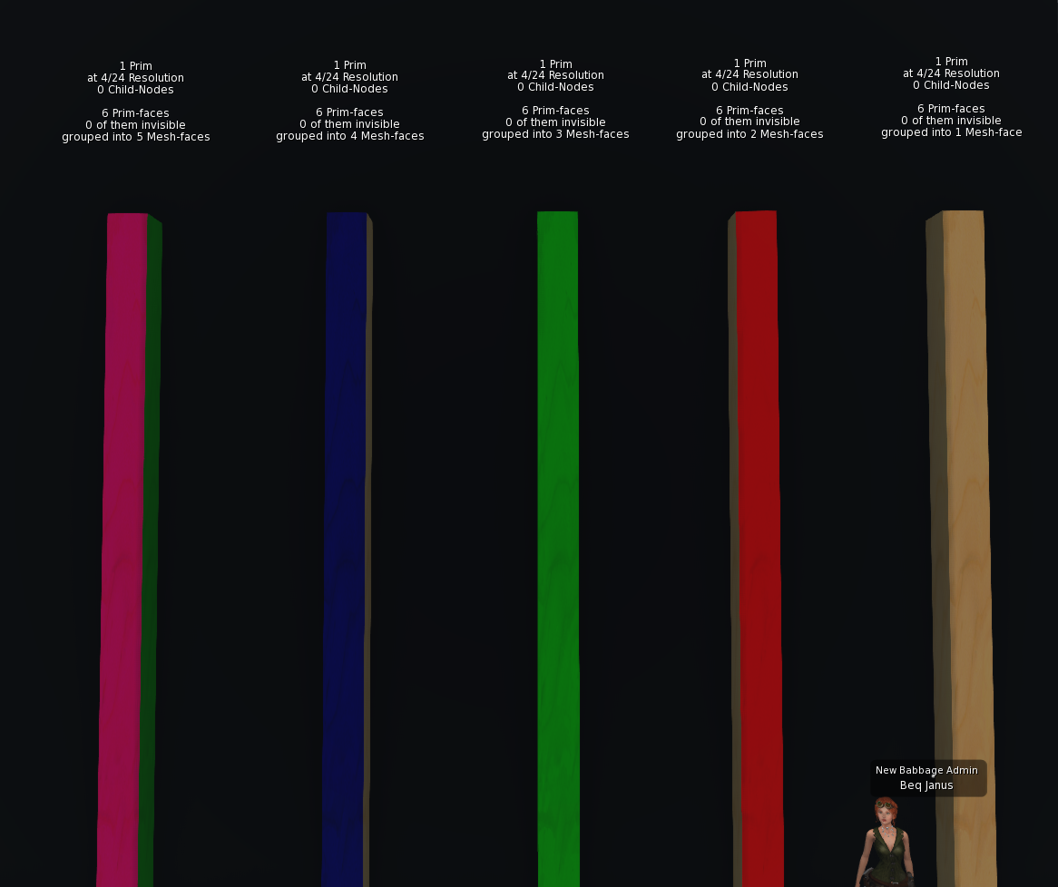
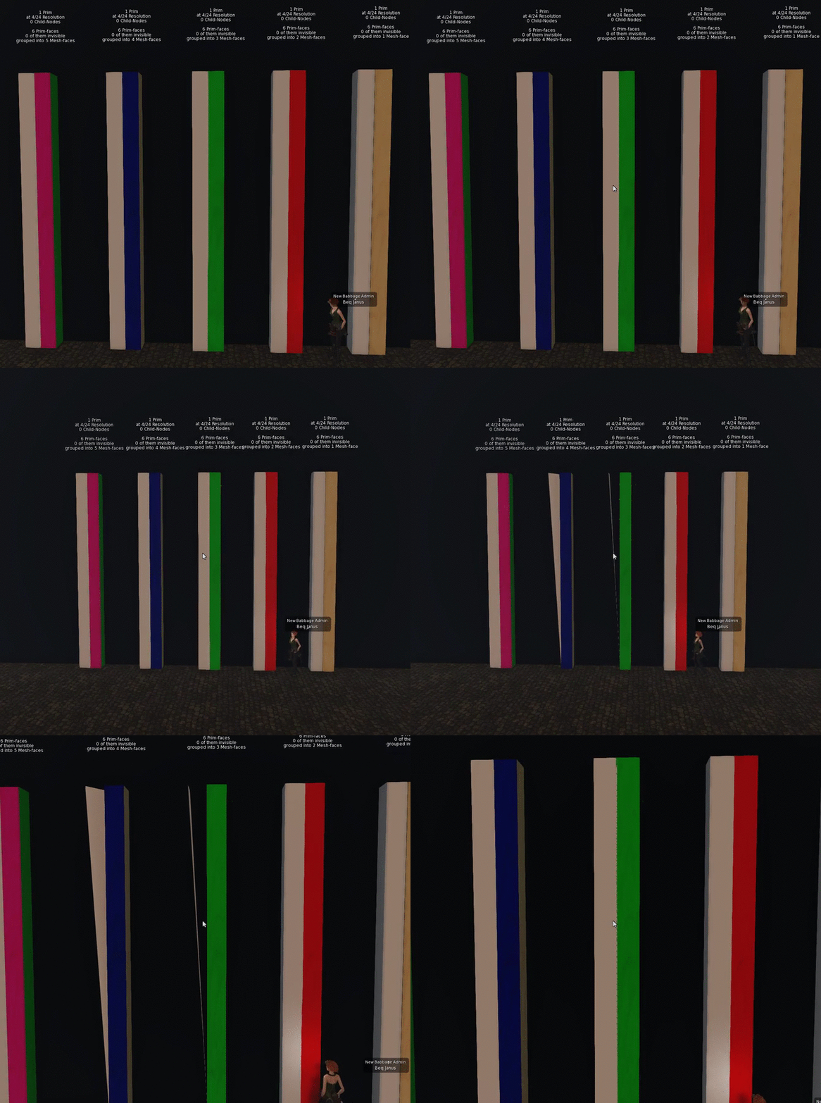
The demonstration is very simple. I created five identical Mesh columns using Mesh Studio (MS). I gave them each a different number of texture faces. Right to left in the image we have the prim models for one face through to five with the MS floating text to confirm this.

They were then each uploaded identically. The model was the HIGH and all other LOD models were minimised so that the object would collapse to minimal triangles as soon as the HIGH LOD went out of range.

Lining these all up alongside their prim equivalents and panning out demonstrates the issue very clearly as the following gif shows.
I hope that this helps make the issue a little more obvious and if you are only now learning, or being reminded of this, then please share as widely as you can so that people are not accidently impacted by it.

Bye for now

Love Beq
x