Showing posts with label New Babbage. Show all posts

Friday, 20 October 2017

My life in lamps...

As I noted in my previous blog I finally got around to creating a set of items for sale. The Antique Radiators were the "sale item" for the Decennial event but I also needed a hunt item. The theme of the hunt is Timeless, the event and the hunt celebrate 10 years of Fallen Gods in Second Life, so I wanted something that also meant something in the theme of time and growth. The item I chose will be familiar to those who have known me for years or who have read my articles in Prim Perfect.

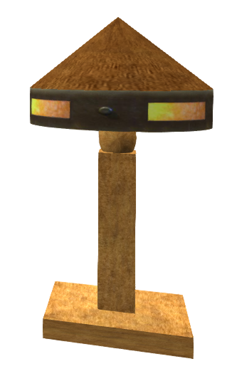
Back in 2007, I made myself a lamp, based on a rather lovely Arts and Crafts period design from the Roycroft movement. A simple but elegant design that could work as a low prim lamp for my undersea refuge in the Vernian Sea in New Babbage.


The very first version is shown here on the left. A gloriously extravagant 8 prims, 2 of which were a bizarrely flickering animated candle flame where the bulb should be. The rim texture cut from a photo of the lamp in RL and recoloured to look as though it was lit up.


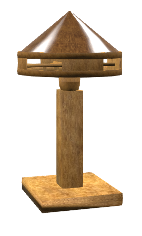
As SL and I both grew, I rebuilt it in around 2008 using "the latest technology", reducing the 8 prim lamp to a glorious 3 prim sculpty based model (right).

The lamp was more or less identical in form to the prim version and created using an Inworld sculpting tool called SculptCrafter which in its way (despite being made by a different person) was a forerunner to tools like Mesh Studio, converting prims to sculpts, which it spat out in chat as a uuencoded text stream which you pasted into your preferred decoder to get the expected sculpt texture. A really neat solution to not needing an external service in fact.


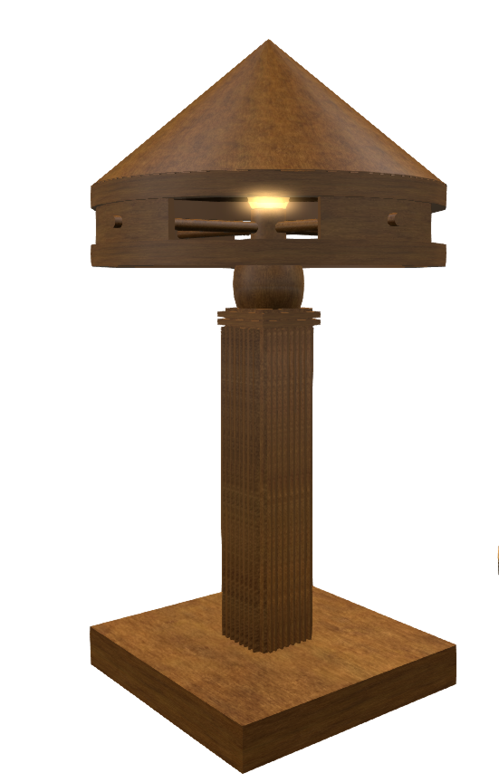
Then in 2012, I was asked to write articles for Prim perfect, demonstrating that Mesh and prim building were not necessarily at odds, the articles built upon a blog post I wrote on inworld mesh creation for which I built the version on the left. The model was created using the excellent and highly under-rated Mesh Studio. The project was a little artificial I added heavy metal fluting to the sides of the stand giving it a more Art Deco feel than theo original RL piece having challenged myself (and the tools) to improve upon the 3LI sculpty in both looks and land impact. The lamp was also used to explain generated LOD models and how handmade LOD models are essential to really efficient and well-structured meshes.

The result was a credible (I think) demonstration of the tool, taking a detailed 110 prim model with all my metal fluting and additional details and producing an efficient 1LI Mesh with Strong LOD characteristics.

It's been five years since that project; we've seen the introduction of many new features, materials being perhaps top amongst them. And I have started to confront my personal daemons, tackling my insecurities around artistic ability to improve my texturing skills, face down the fear of Blender and it's mythically horrendous UI (hint: it really is not anything like as awful as people will lead you to believe, it just takes a little practice). And so it seemed fitting, that to celebrate 10 years of my friend Alia's wonderful creations, with a nod to my own 10 year anniversary too, that I should once again update the lamp.

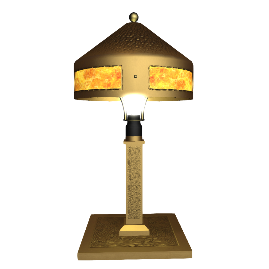
The 2017 Roycroft style lamp is available as a hunt prize during the timeless hunt and may become available later from the Verdigris store, in a variant form.

At 1LI, we now have a lamp that retains much of the hammered effect detail of the Roycroft originals. The detailing employs Normal maps for those with Advanced Lighting, but also bakes and additional Ambient occlusion to the texture to give some of the effects to those without that feature.
Materials are used for the bakelite bulb holder as well as the metallic lamp itself, and the mica panels use the emissive mask feature of the diffuse texture to give a more realistic glow when the lamp is turned on. It was important of course that in an item of this scale it retained its shape and volume as the LODs decayed, which became a little war of attrition when the lamp nudging over the 1LI threshold.

The Decennial event and the excellent Timeless hunt are still open and I would encourage you to pay a visit.


Thursday, 5 October 2017

Verdigris by Beq - OMG I have a store!!

It has only taken me 10 years to get around to doing this; but I finally have a store, with a name and actual "stuff" in it. Well not much stuff, yet, but I'm working on it. It will ultimately live in my old factory build in Babbage Canals

So what brought about this monumental event? To be honest no one thing, I've been gathering steam towards this for a while, but all those normal excuses like Fantasy Faire, joining the Firestorm team, RL School and family etc have been a convenient cover for my laziness.

Then at the end of August, I got a notecard from Alia Baroque. Alia, as Faire lovers will know, is a crazy, wonderful designer who is best known for Fallen Gods skins, his awesome Fantasy Faire regions and err... Flamingoes. It turns out that Fallen Gods have been making skins for ten years now and Alia decided to celebrate as only Alia can, by promoting his friends through the Decennial shopping event and the Timeless hunt organised by Alia and his wonderful partner Sonya.


And so it was, with a little coaxing from Sonya and Alia I committed to taking a stand at the event and to participating in the hunt. This commitment threw me into my usual dilemma of confidence. "What on earth would I make that anyone else would want?"

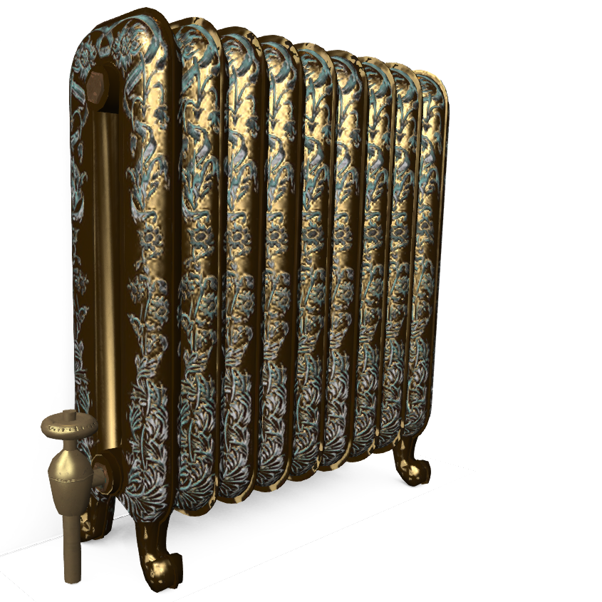
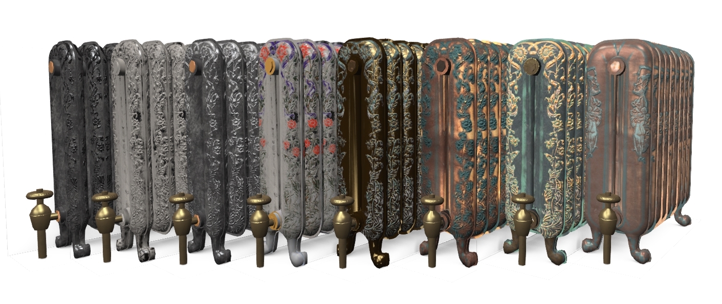
In recent times a lot of my building, all of my building really, has been focussed around region scale designs with a limited mass market appeal. So after much soul searching and gnashing of teeth I fell back upon my early roots, making smaller items, for my own use, looking to produce artefacts from the Art Nouveau and more generally Victorian and Edwardian eras. The result was two items, the first was a prize for the timeless hunt, an item both brand new and yet completely familiar to those who know me. I'll talk about that in a separate blog as the hunt is still in its early days. The second item is the first official Verdigris product, a range of radiators based historic designs and presented in a number of material finishes.

Initially available only at the Decennial event itself these Radiators will later appear in my inworld store, and on Market Place, hopefully in time for winter.

Each radiator is mod/copy and thus can be scaled to your heart's content, It is 1LI at its standard size and remains below 5LI even when scaled to larger proportions.

You can find my stand and those of the many awesome creators that are celebrating Alia's ten year anniversary at Decennial


Bye for now, love 

Beq

X


Saturday, 17 September 2016

How low can you go? An optimisation war story - Part 1 HIGH LOD tuning.

Einstürzende Neu "Babbage" bauten

A bad play on words to start a long blog :-)

When I walk around my beloved New Babbage I see far too many new Mesh buildings that collapse into a garbled mess as soon as I put my settings to anything close to that of a default user. Older buildings that are sculpted I can understand but with Mesh there is not really a good excuse.

So ask yourself, are you guilty of not paying attention to the "other" LOD models?

One of the drivers towards this is keeping low LI and an assumption that creating a proper LOD model away from the HIGH LI is both a lot of work and costly in terms of LI. In this short series, we will discuss a recent project and some of the strategies I used to meet a low LI target and ensure that the object remains visually consistent but more important a viable solid silhouette at a distance. It is not going to be an all answers guide to efficient building, and I am in no way the right person to write such a thing but hopefully you will see, through my recorded pain, how you might tackle a challenging build, achieve respectable LI and preserve credible LOD behaviour.

For an older guide to creating your own LOD models, especially those using Mesh Studio, might want to take a look at my 2012 blog Too much information - making your own LOD models

About LOD and how it is observed

As the above blog explains the LOD that will be displayed is governed by the radius of the object and the distance of the observer from it. But that is not the full story; there is a multiplier that can be applied that makes the LODs appear at a higher resolution for more of the time. This setting is known as the LOD Factor (aka RenderVolumeLODFactor).

Once upon a time, setting your RenderVolumeLODFactor as high as your viewer allowed was standard practice, you can still buy outfits whose associated readme tells you to do this to maximise your experience.

The LOD factor setting was used to combat the terrible construction of many sculpty based buildings. The fact of the matter, however, is that while users of Third Party Viewers such Firestorm can set this as high as 4, the Lab viewer is limited to a maximum of 2 and defaults to about 1.5 depending on your graphics capability. It is therefore, important to consider carefully your tradeoff between more detail in the HIGH LOD and better presentation in the lower LODs. In most cases, the MED LOD is the one that people will be seeing the majority of the time.

Managing Level Of Detail is still considered a dark art by many. I see far too many Mesh builders, both experienced and new that don't understand the factors that control when LOD changes or perhaps more worryingly choose to forget that most people in SL don't touch their Advanced Graphics settings. Building with low LI is easy if you don't care what it looks like to others, however, when building for architecture, anything that is going to be seen outdoors, in particular, careful attention to the LOD levels is very important to the overall quality of your build.

What should we be aiming for?

LOD
Primary goal
Bullet points
HIGH
Close up. Full detail. This is the only mandatory model.
  • Details
  • Clean Mesh
  • Strong basic outline with finer detail.
MED
This is arguably the most important Model. It will be seen by most of the people most of the time.
  • Same strong basic outline.
  • Flatten recesses
  • Remove interior faces and anything too thin to be seen from further away
LOW
This is only ever seen at a distance, it is important that the general silhouette maintains the volume of the build to stop the "crumple" effect
  • Maintain volume
  • Focus on the silhouette.
  • Flatten all detail focus on outline only
LOWEST / IMPOSTER
The last of all. This is very hard to deal with as a model and often the imposter solution is best.
  • Maintain silhouette where possible consider using spare material slots for imposters.

An arabesque challenge

I recently undertook a request from a friend who is busily rebuilding his property in New Babbage.
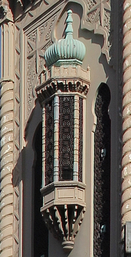
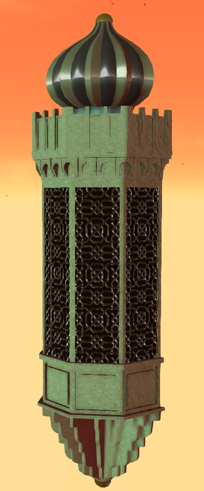
He desired an arabesque bay window, modelled after a theatre in Melbourne.

"No problem", I said. "what does it look like"

The photo shows the real life bay window. The onion dome on the top is reminiscent of the onion domes that I used in Aurora - my 2014 build for Fantasy Faire no doubt one reason why the job came my way.

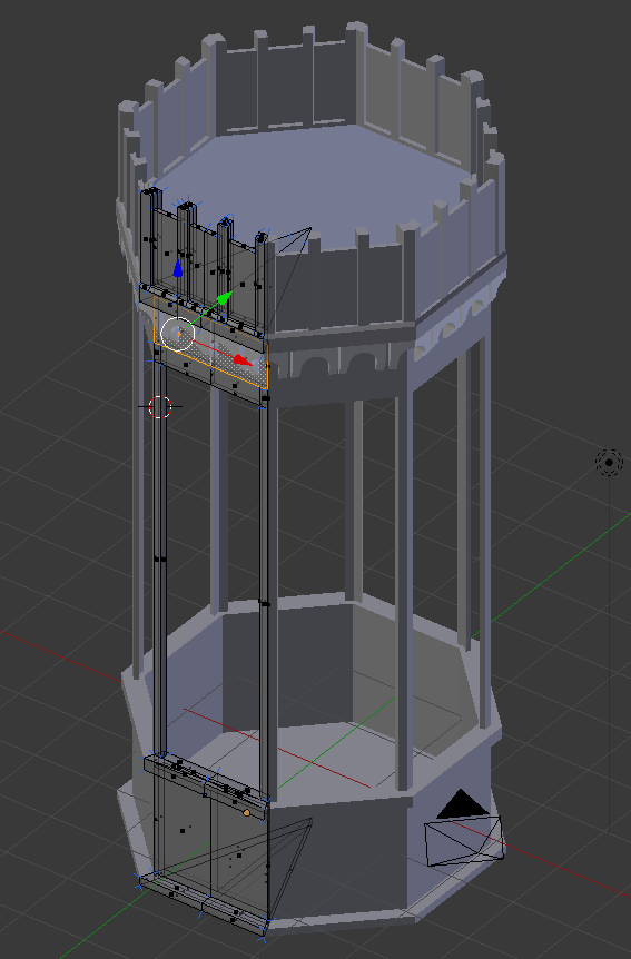
I often start a build in Mesh Studio but as I have been putting effort into my new workflow tools lately I decided to make this from scratch in Blender, so I set to work making an octagonal frame that I'd halve later.

I had of course forgotten two very important questions. "How big is it and how many LI do I have to play with?"

The answer came back the next day, it would need to be 9.5m high, 2m wide and about 1.5m deep,

"OK, that seems reasonable, what about the land impact budget..."

"About 2LI?"

Much teeth-sucking followed, 2LI for a large object with high detail was not an easy task.

"ookkkay." I said not wishing to give up without at least trying.

You may recall from previous blogs that the LI calculation is impacted by the scale, moreover, the issue is compounded by the realistic distance that an object will be seen from, and by whom.

If you are making a desk lamp, that will only ever be seen within your tiny office, and only ever seen by yourself, then you can take all manner of shortcuts that ignore the lower LODs and assume that the viewer has adjusted their viewer LOD multiplier etc.

In this case, though, we have a perfect storm of LOD and LI demands.
  1. Reasonably large in scale
  2. Visible from a distance as it is an external component.
  3. Seen by any visitors to the sim whose viewer settings cannot be "presumed"
  4. It needs to be low LI.
Large size means that the triangle rich HIGH LOD will be visible for a larger distance and this will put up the cost. The biggest cost is, however, going to be the MED LOD which will be visible across a very large part of the region, and thus is going to need to look pretty good.

Advice for the faint hearted

The following section *is* very long winded. It is about driving down the LI from an initial 15+ LI trial upload to the low target of just 2LI. I'll show you the working and comparisons but..

You don't need to do this to achieve results.
I find measurement is the best way to track your progress but that's just me. You can of course try these things on your objects and see how you get on without needing to measure every deatil.


Thinking about budget.

Let's do some quick maths then....no let's not, I wrote an AddOn for this...

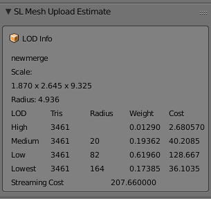
Using a Cube of the right dimensions we find the following information
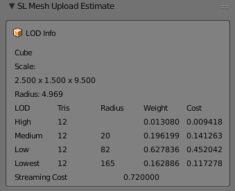
A radius of almost 5m means that our HIGH LOD model will be visible to the default user setup within 20m. Now given that this is nearly 10m high and will sit on the side of a hotel, we can assume that many users will be seeing it from further than 20m away. So as we suspected the MED LOD needs to look good. What's more, the LOW LOD will kick in at 82m. Now this is New Babbage, visibility of 82m is unheard of but we can expect people to want a viable silhouette, so we'll have to make some effort on the LOW LOD too.

We know that my plugin values for the cost are over estimating but the proportions are probably not far off. Triangles in the MEDIUM are going to cost about 15 times that of the HIGH, with the LOW costing 3 times that of the MEDIUM

In fact, we can check this using an inworld analysis script.

Radius    Total LI  HIGH LOD   MED LOD    LOW LOD    LOWEST LOD
4.968652  0.729080  0.154618   0.348042   0.216630   0.009789
LOD sizes in tris :      197         30          6          1
LOD sizes in bytes:     3536        857        476        400
Cost per tri(LI)  : 0.000785   0.011773   0.037674   0.009767

We see that the ratio between LODs at that scale is:
HIGH/MED    15:1
MED/LOW      3:1

We can also see that our budget of 2LI is going to be tough.
SL rounds down so we can creep up to 2.5.
2.5LI is 3571 triangles in HIGH LOD.
For every triangle we put in the MEDIUM LOD we must sacrifice 15 in the HIGH
For every triangle in the LOW LOD we must sacrifice 45 in the HIGH

What is more, we are working on a symmetrical Mesh, every triangle we place on one wall becomes 4 in the final mesh so our full budget per wall is 892.

Making a start

I'd started with an octagon using 3 mirror modifiers to take a single face and reflect it up into 8. The idea would be to make the octagon then slice it in two. Very quickly I realised this was the wrong path (slicing a mesh in half is always best avoided) and instead switched to using array modifiers.

The model is built to be relatively efficient. All normal first stage optimisations have been made. The two most common for me are:-

  1. Remove hidden faces.
    This applies to any mesh creating workflow, when you work in Mesh Studio you do this before creating the Mesh by setting the face to be transparent. With Blender, a similar process can be applied. MY method is to create a "fake" material face could DELETEME, assigning any that faces that I find which cannot be seen as I go, deleting them later in the workflow.
  2. Remove duplicate vertices
    As you work you often end up with overlapping mesh and blender has a convenient function to remove duplicates. It has a slider to control the threshold (how near they must be) which is great for tidying up messy joints, but it needs to be applied with care or you'll lose small details by mistake. This is also a job that can take place numerous times in a workflow. For Example, if you apply modifiers, especially mirror or array modifiers, you may get duplicates left. 

I modelled the main body, the crenellations, the dome and the lower corbel separately merging them into the joined model. The result was as follows:-
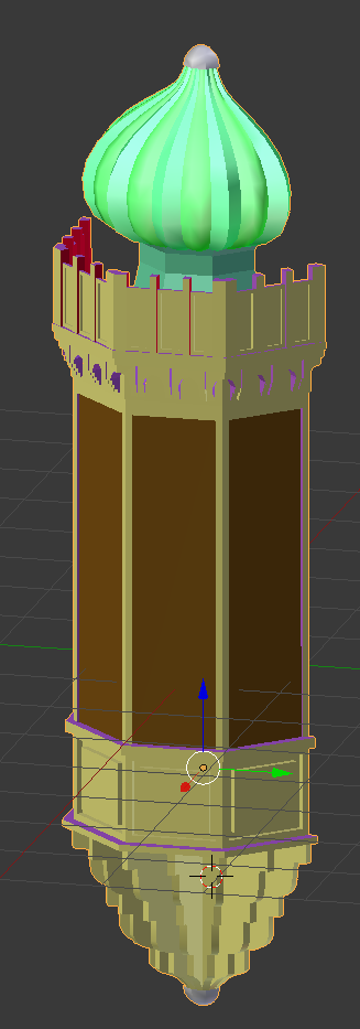


3461 Tris in my HIGH LOD Mode and coming in at around 3LI, now with the error in my AddOn we can suspect that this would be about 30% less. so perhaps 2LI, which will leave us nothing at all for the MED LOD. We are going to need to do some serious work to hit our target and frankly, I don't want to lose any of the detail I have if it can be helped.

Breaking it up - Bespoke optimisation

So what can we do? We've already done the basic stuff. We have a clean looking mesh, we removed all the doubles. So we now need to look at item specific tactics, is there anything about this object that we can use to our advantage?

If we look at the object we notice a number of things. The main body is quite plain. I modelled the fretwork for the window but only used it to generate the textures and bump maps, apart from that it is really just a few inset panels. The crenellations are far more detailed with a curved and stepped arch. Then we have the dome, At first, I reused the old Aurora dome but quickly decided to recreate it from the start, either way, it has to have smooth curves and they are costly. At the bottom end we have the curved corbel another comparatively costly piece.

By linking all of these into one we are paying the price of a 5m radius object when by separating them out we van get those same triangles cheaper. Will it make a major saving?
Let's have a look.
LOD
HIGH tris
Radius
Cost
Notes
Combined
3461
4.94
2.680
All 4 parts joined and dupes removed
Dome
787
1.58
0.062

Crenellations
1650
1.77
0.164

Bay Window
276
2.82
0.069

Corbel
784
1.65
0.067

Separates Total
3497

0.362
Notice the slightly higher tri count.

So why would we ever join the mesh? The combined mesh has a couple of things in its favour.
Feature
Joined
Separate
Server Cost
Always 0.5
0.5 for each unit. In our case 0.5 x 4 gives us 2LI Inside out target so perfectly acceptable.
Texturing
Eight texture faces
Eight faces per unit. A lot more work perhaps. Also a lot more flexibility
Upload cost
Not really sure this matters
What's a few Lindens between friends?
LOD switch
A biggy. The LOD will switch based on the BB of the single unit
The LOD will switch independently for each item. This is good and bad. It can mean that the larger features stay as HIGH for longer than the small features. All the more reason to design good quality LOD models
LOD calculation
The crux of this issue. All triangles are going to be costed at the size of the overall object. Imagine a full-scale house with a mesh door knocker.
With the parts separated into sensible chunks we pay a more appropriate price and can choose where to place out details. This has worked incredibly well on our broken up window the High LOD coming in at about 13% of the merged

So what have we achieved, so far?

We had a hard target to hit at 2LI for a large and potentially fiddly mesh. My first "sketch" was coming in at 15LI with no other LODs and that seemed to suggest a big problem ahead. But by the time we've sanitised the Mesh to just what we needed and nothing more we were down to the low single digits. 

We then made use of the fact that this object has some large flat expanses that unhelpfully push up the scale. Breaking that down we have now reduced out HIGH LOD exposure to less that half an LI. Leaving us up to 2LI (remember LI gets rounded to the nearest whole so we can go to 2.5) for the remaining LODs. 

The bad news is that because we have broken this into smaller parts we now need to consider that the LOW LOD might be seen from nearer than before and a larger budget might be needed there.

Coming soon...

Next up we will look at the MED LOD model and see how we can keep our design goals and our LI budget aligned.


Monday, 1 August 2016

Mixing planar and non-planar faces in Mesh Studio

Something for the Mesh Studio afficionados today.

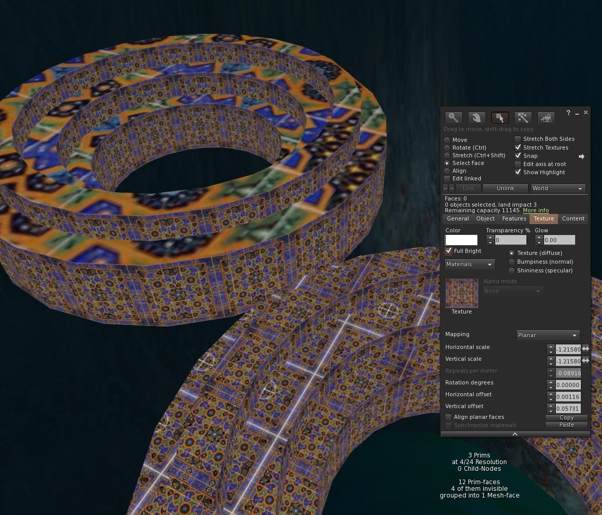
Mesh Studio has a "feature" insofar as it does not detect the mapping mode of a prim face. This results in an incorrect Mesh import later. First, a quick illustration of the issue and then how to fix it.

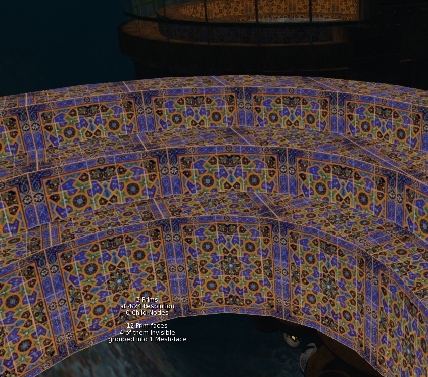
It is time to do a little more work on a slow burn project to gradually rebuild parts of my ancient underwater home. I've only got half an hour to spare so I want to Mesh the steps in the moonpool, so that I can safely apply some materials without it blowing up.


I quickly copy the existing object, tossed in the joined mesh script, eliminate a couple of the unnecessary surfaces and hit "Mesh".


A few moments later and I have it imported, apart from being a few Lindens poorer, we are good to go,aren't we? I drag the texture onto the Mesh and....ugh! That was a waste a Lindens, the texture UV mapping is wrong.

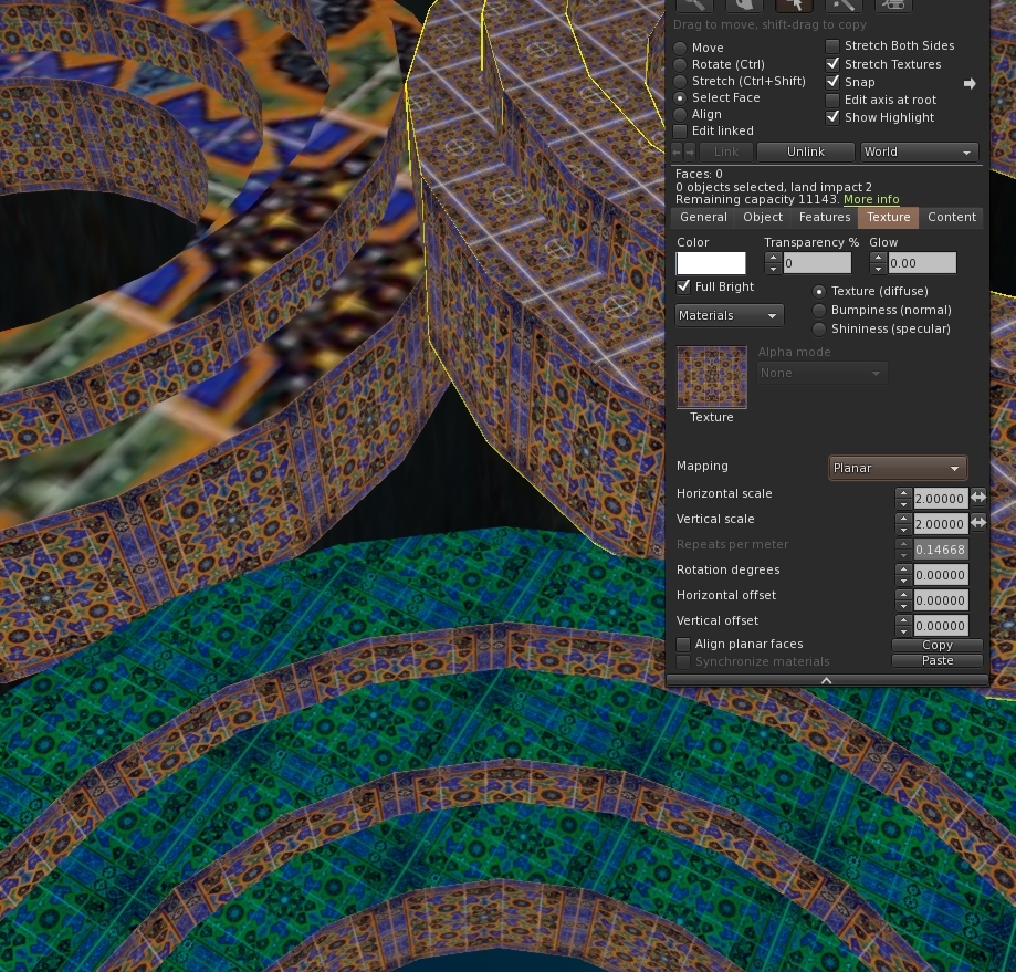
 A quick check of the source model and the reason is clear. While MS quite correctly noted that the texture UUID and the tint are the same on all the faces, it failed to note that top faces were planar mapped, while the inside cylinder faces were default mapped.
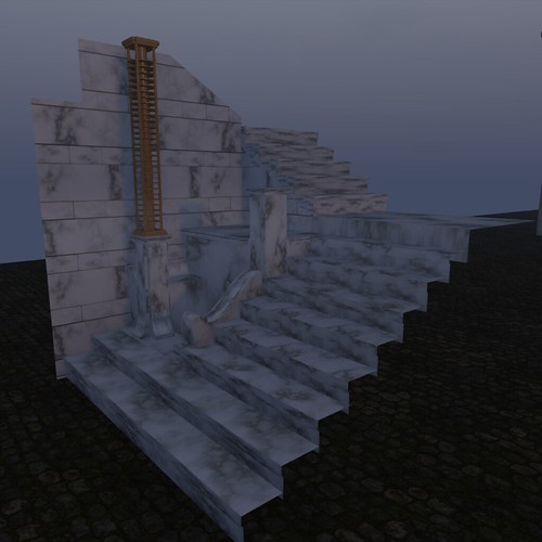

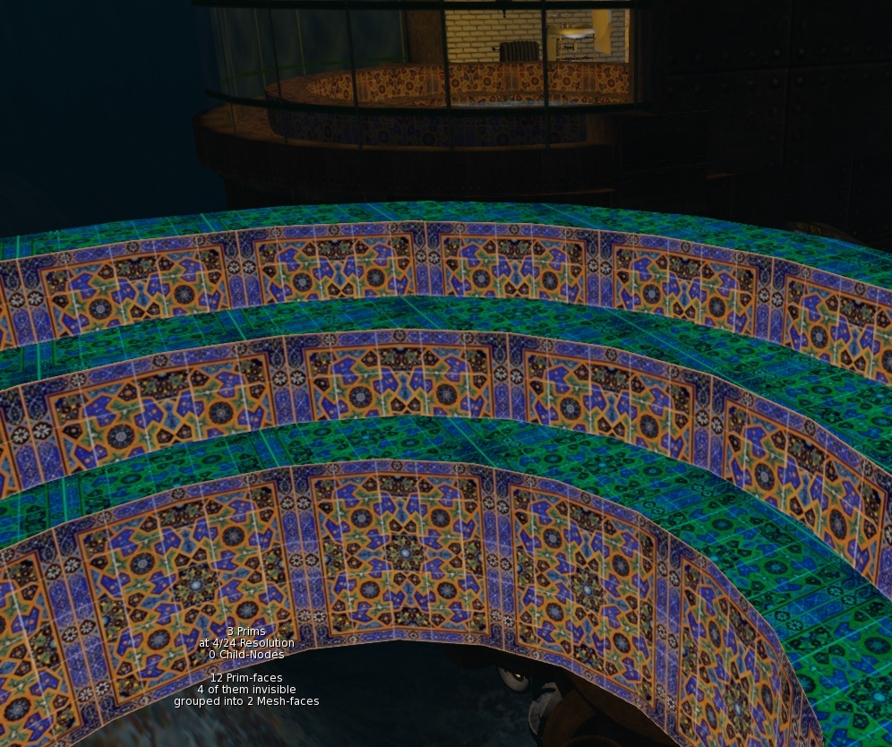
Happily, this is easily fixed. All we need to do is convince MS that this is a different face to the other one. We can do that by changing the tint value. A quick lick of paint and we find that MS now correctly sees this as having two mesh faces. and we are ready to splash another few lindens on an upload.
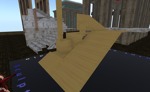

Rezzing the newly uploaded mesh we gleefully drop out texture on it and for a moment our hearts skip a beat. It still looks the same. Then we remember, it's called "default" mapping for a reason and sure enough highlighting the face and setting the mapping mode to planar snaps it back into shape.


And so there we have it. When mixing planar and non-planar with the same texture just make sure that they have a different tint.

If you have a larger build that will be painful to convert manually I have written a script that runs through the material list, identifies clashes and auto-magically changes the tint. Ping me an IM inworld and I'll send you a copy until I get around to putting it up to download somewhere.

I'm heading out for a couple of weeks so take care and more blogs when I return.
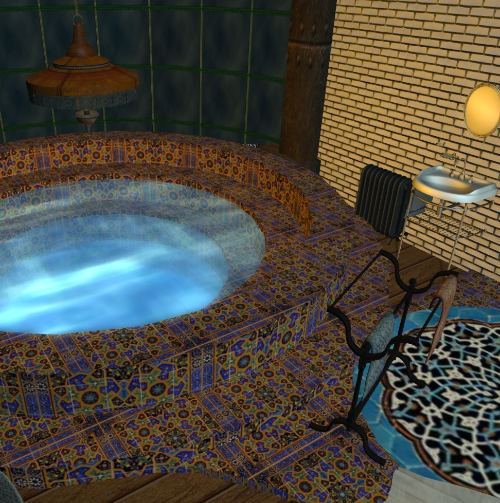
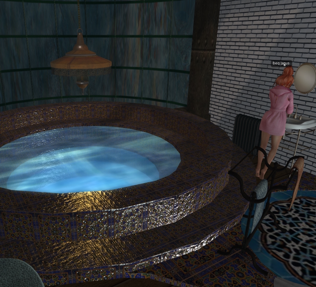
For now, I'll close with a quick recap of the steps with some materials applied to give the tiles that glazed shine.A bit overdone but mission accomplished for the Mesh at least.

Love

Beq
x


Thursday, 20 February 2014

So what are the laws of Physics?

I've been reworking the Mansard Roof on Maison Horta in Mesh. It is currently a sculptie created a year or two back using Sculpt Studio. The challenge is to get the LI low and have a reliable physics profile and resilent LOD. Nothing new there.

Sculpted mansard with sculpted stone dormas
 I detached the dorma and made a prim model using simple wedges for the most part. The final model being 13 prims with 5 distinct texture faces. I generated the Mesh using Mesh Studio and then switched to Blender. 

The Mesh Studio model

I knew that some of my joints were inaccurate, this was in part my sloppiness and in part lack of precision in the shear and taper options. Blenders remove doubles command allows you to merge vertices that are in close proximity and when used sensibly can tighten up all those poor joins.
Blender model - perspective makes the angles look wrong.

The Blender model can be further optimised, by hand editing we can eliminate unnecessary vertices that lie on un-attached edges (such as the top edge) and their associated geometry, the aim as always is to look for new ways to divide up the shape into triangles. Even now there are a few more savings that could be made but I prefer in this case to avoid long thin triangles.
Optimised by hand.
For medium LOD I can use my intimate knowledge of the use of the item to make firm decisions. The interior will never be visible from far enough away to drop to medium LOD, therefore I can cull all the interior faces. I make sure to keep a triangle with the correct material assigned though to ensure we comply with the basic Rule of SL Mesh that all LODs must share the same materials.

For Low LOD, I am going to use the same model as Medium. This will push up my streaming cost but so long as I stay under 1.5 I will be happy, and it will ensure that the house remains good looking for those spectacular New Babbage roofline shots that people love.

And so... physics. The point of this blog. In second life the laws of physics or not so predicatble as those in in real life. I've noticed this in the past but rarely taken the time to explore much. You may have noticed that when you import a Mesh the calculated physics cost in the upload dialogue is close to useless and this is true of both TPV and Lab viewers.

So how do we get the correct balance of physics shape to physics cost?

Given that my next article in Prim Perfect will need to examine physics, I decided to experiment. The first and simplest task was to use the model itself. In this instance it is actually a pretty simple Mesh so we'll see what happens.

Firstly, we specify the model as before and then for physics we select "Use HIGH". We will not touch analyse. As you can see the uploader predicts a physics cost of 0.440. Brilliant. All good then.

Using High LOD model, No analysis.

But when we get it onto the grid and rez it what we find is a different story...
The physics cost is not 0.44, it is nothing even close to that. The physics cost has rocketed to 1.4. It all works nicely though. But perhaps if we were to use the analyze function we'd get better results. maybe that elusive 0.44.

In the screenshot below we see the upload screen. This time we have selected the Analyse option. We are using the Solid method as in general this is best for block builds (use surface for curved builds). In pracatice you can try the 3 methods and see whcih gives the best (simplest) physics that looks right.
The analyse function has returned and told us that the physics mesh has be decomposed into 6 hulls. That seems plausible so we can accept that and go ahead with the import.
another aspect to note however. The Analyse function has pushed our import cost up. It is now going to cost us 13 Lindens whereas before we only paid 11. What is going on?

So now we have imported the mesh with our highly analysed decomposition, surely we must get better results in world....Errr no.

This is odd. We have used the self same mesh and rather than letting the system make some estimate (using an as yet unknown methodology) we have let the Havok system break up the mesh we provided into the most optimal collision shapes it can. The result, our physics cost has rocketted from 1.4 to 2.6 taking our overall LI from a rounded down 1 to a rounded up 3.

If a non-analysed collision mesh can be much lower (in some cases) how does that occur?  you might be tempted to think that the non-analysed collision mesh is inferior. Well it does not seem to be. I can happily walk back and forth through the gaps. But when we take a look at the Metadata view of the physics we see something very peculiar indeed.

Analysed Mesh with physics shape in blue
First, let's look at the physics model generated for the analysed mesh. A nice tight fit, and near perfect match to our physics template. This may be overkill for out needs but we'll come to that later.

Sure enough we can walk through the doors and if we walk into the wall we will slowly climb the slope or walk on the spot on the flat side.
 No surprises at all, physics mesh doing exactly what we expect, and a good job too given how much we are paying for it in LI.

Now, let's take a look at the physics metadata for the non-analysed physics.


Non-analysed mesh with physics in blue
Wait a minute, that's not what we asked for, that's not what we are observing either.
The physics shape revealed by the "render meta-data" option in the viewer is showing us what appears to be a default convex hull. But that cannot be right. I can walk through the doors and collide with the walls with the accuracy of the analysed mesh above, and yet the viewer is telling me that the physics shape does not even know about the doors.

Is this a viewer bug? I have not tried the Lab viewer yet.

trying to walk through with "convex hull" physics
The last couple of images show the difference in behaviour of the same object. Firstly with "convex hull", secondly with "prim". as you can see, with "prim" I can walk through the gap. This is not news... However, the physics shape is the same in both cases, you can clearly see that I am standing "inside" the supposed physics shape

walking through the same model but using "non-analysed" prim physics.


Thursday, 27 December 2012

Getting Physical - Revamping a staircase

One common feature of late 19th Century middle class urban houses in Europe was the entrance staircase. In the usual manner of design, a kitchen and scullery occupied the streetside of the ground floor, the main reception rooms were therefore on the floor above the street level, the Bel Étage. Not one to conform, Horta took this "standard" and reinvented various aspects. Reorganising the groundfloor to give more space but also making the entry staircase a real feature piece. As one entered the building the double doors were swept open and the visitor was met with a stunning marble staircase lit from above by an ingenious light well, making it both light and welcoming, very different to the darkness often encountered inside the deep set terraced town houses.

It was always important to me to create that sense of welcome, the idea that you were entering something different. Though as in all my earlier attempts skills and tools both left me to make compromises.
This is a photo of the first version of the stairwell. This predates sculpts and is fully prim built. The brass coloured column in the middle is my low prim attempt at recreating the lovely column radiator that Horta installed to take the chill off of the stone stairwell.
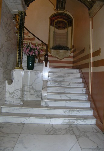
The photo above shows the real life Maison Horta and gives an idea of what I am trying to achieve.

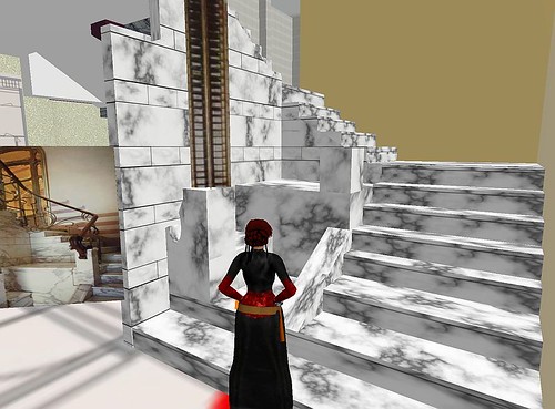
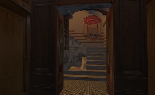
This is how it has looked for the past 3 or 4 years, the only significant change since the 2007 version was to replace the prim built stairs with sculpted ones (a real saving back then!). There are some significant missing details not least of which is the curved marble  detailing that forms the side of the staircase for the first few steps.

Today I rebuilt the stairwell using a combination of Mesh Studio and Blender. Blender was required for the curved marble that could not be produced from prims.
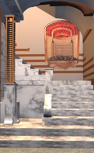
Here we have the 2012 version of the same stairwell. much closer in form to the original now with a proper mesh rendition of the radiator too and crucially, even with the separate meshes for the radiator and the curved marble, it still only incurs a land impact of 5 compared to around 15 for the previous version and closer to 25 for the original.

However the purpose of this blog was not simply to track progress but also talk about physics. There is a lot of confusion over physics in mesh and how to define it, but simply defining it isnot the end of the story either. By default once you import the physics is not actually enabled properly.

The default mesh physics is something akin to taking your object and stretching cling film over it. it will tend to stretch from one extremity to another and not follow the shape you have lovingly crafted. This is what is know as a convex hull. Any mesh when first imported whether you have defined a custom physics model or not appears to have its physics type set to convex hull.
Here we have the finished stair well ready to be deployed. We can use the viewer to help us see what the physics looks like for any given object. Make sure you have the debug/develop menu enabled and then select "render metadata" and tick the "Physics Shapes" option.
In the image above I have told the object to use the convex hull physics. This is selectable from within the features tab of the build menu and is labelled "Physics Shape Type". By default you may see only two options, "convex hull" and "none". As you can see the convex hull drapes itself over the mesh and is far from useful. If you select none then the object effectively becomes phantom and you can use the old fahsioned trick of invisible prims. However, there is a better way.

The better way, is to build your own physics model. Don't worry it is not scary and all you do in fact is exactly what you might have down with a sculpted prim and invisible prims. Create a model that matches the physics you wish to define. the simpler the better as each face will add to the physics cost of the mesh upload and therefore influence your overall LI.
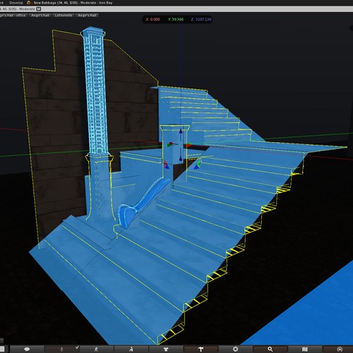
In the photo above I am working on such a model. Note that I am only defining the surface that I want to be "physical", so ramps for the stairs are that bare minimum. I have also chosen to go crazy and define some physical presence for the columns and other decorations. Everything that would never be reasonably expected to be touched by an avatar can be made invisible. Once you have made this model drop the Mesh Studio script into it, set the settings to the lowest level and make your mesh.

The physics mesh is applied at upload time and cannot be tweaked later, it is important (and I discovered this the hard way) to ensure that the bounding box of the physics matches the bounding box of the model. If there is any disparity when the model are overlaid they will no marry up properly.

Now let's look at the results of applying a custom physics mesh using the viewer tools again.
In order to see a custom physics mesh we have to tweak the physics type setting again as before. If your mesh has a custom physics mesh included then you should now have a third option available "prim". This may seem rather obscure and I would agree, however selecting "prim" as the physics type, enables the physics map defined in the mesh model. As you can see the physics mesh perfectly matches the model I made and has been overlayed on top of the visual mesh. The result is nice sloping stair ramps and a few extra details.

Hooray.

I hope this helps a little, to explain the peculiarities of mesh physics.
Be careful mesh can be slippery at times.


Revisiting an earlier project - Chimney stack 2012 and some history

Those who know me inworld will know that my home "Maison Horta" has been around for over 5 years now in some form or other. Over on my flickr account you can find various images from the original construction phase. It was a tough project, I'd never used Photoshop and barely had I joined more than a handful of prims together.

One of the external features that vexed me at the start was the chimney stack. Through limited photographic evidence and drawings I had a good idea what was needed but on a tight prim budget (I had only about 400 prims for the entire build back then) with no sculpties it was going to be ugly. A complex arrangement of varying heights made it costly to reproduce and so I compromised with a two prim construct each textured, and it *was* ugly.

2 years later I gave in to my general concerns about LOD in exteriors. Babbage is often shot as a series of long sweeping rooftop views, I did not wnt to be the one with the large egg on the side of her house but when the use of RenderVolumeLOD debug setting became more common knowledge and practice amongst photographers and visitors this was less of a concern. I built the basic stack from prims using SculptCrafter, the result was a definite improvement but far from ideal, as it always looked a little awkward, catching the light in peculiar ways...

And so it was that the chimney was one of my first ever Mesh projects using the wonderful Mesh Studio. Even before I had a play with the Roycroft lamp featured in earlier blogs I took the SculptCrafter prim buil;t model, ripped the SC scripts out and dropped in the Mesh Studio one. The result was much better, a far neater looking object, with better LOD behaviour and lighting. Being the first project I had undertaken I knew little to nothing about levels of detail, about hidden geometry and about a number of the Mesh specific nuances that I take for granted now. The result was a very acceptable but overly costly (2 LI) and somewhat plain.


Not feeling much like undertaking a large task I decided to re-examine the chimney and see if I could reduce the LI, improve the LOD and add some depth by using fake shadow prims inside the openings.

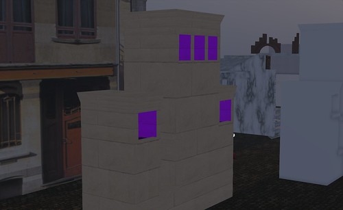
The first task was to dig out the old model and update it. The purple material here will represent the sootier inside faces of the chimneys. You can also see a hint of a black material too. This is a the material that will form the shadow layers.
Shadow layering is an effect I sused in the 2011 RFLSL New Babbage winter city build to add the perception of depth and shadows to the viaduct and other tunnels. The effect is simple to achieve and remarkably effective.
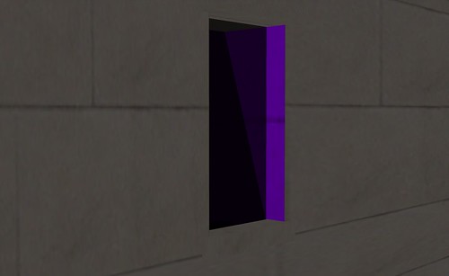
The image above shows the effect a little more. I am experimenting a little here with an angled shadow.
The shadow prim is a stack of semi transparent (I typically use a dark smokey texture) texture faces. In the past I used planar sculpts with each set of four vertices forming one layer of shadow, if each layer is 4% opaque then by the time you stack 10 layers you have a fairly dark (~40%) shadow. In a tunnel, having these layers through the entire length allows you to control how far ahead the user can perceive things making the darkness seem all the more real.

In mesh the same can be achieved in much the same manner. For the sake of experimentation I decided to make it possible to cam down the dark chimney, without the shadows, SL would simply display large empty holes.

Back to the chimney...

One of the issues before was that I had left a lot of hidden geometry in the mesh. Hidden geometry is mesh vertices and surfaces that do not really exist but are a by product of using Mesh Studio and building form prims. Mesh Studio will not create Mesh for points that the fully transparent. therefore, it is a good habit to remove all the hidden mesh faces by making them transparent.

By far the easiest way to do this is to highlight the entire object and make it completely invisible.
The image above demonstrates this. If you look closely (or check the full size image on my flickr) you can see that the Mesh Studio script is tracking my progress and tells me that there are 310 prim faces of which 310 are hidden.
Now, using whatever method you prefer, select visible faces and set their opacity back to normal.
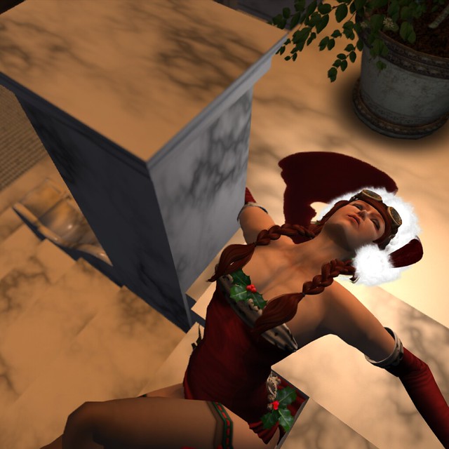
As you can see, just because I am building it does not stop me from dressing festively. I just take extra care not to catch my dress on sharp edges, or spill texture paint on me.

The process can take a while, especially on a complex object. I use ctrl-alt-t to reveal hidden, and then using select face slect a bunch, set them to visible and repeat until I can see no unwanted red.
Here I am part way through the process and the Mesh Studio script is telling us that we still have 248 faces hidden. The more the better, the idea is to only reveal those that absolutely need to be seen.
Once we are finished we can create our mesh and install it.
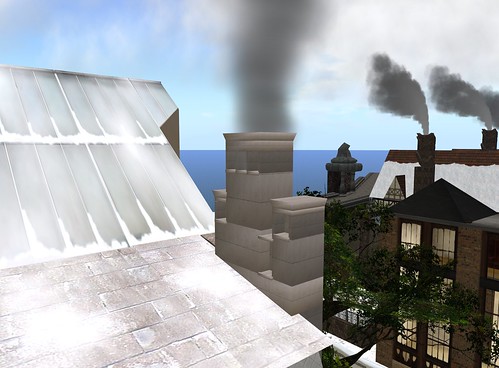
And here we have the Maison Horta chimney stack 2012. It is now reduced to 1 LI and has the improved texturing to the inner surfaces and proper holes you can cam down. Beware of urchins.
There is a 2013 project evident though. the external texture is rather lacklustre, either some more materials to add some variation to the texturing or a fully baked texture are in order...

Have a good New Year everyone.