Showing posts with label collada. Show all posts

Tuesday, 20 September 2022

Announcing Local Mesh

Update: January 2023 - Local Mesh is now part of the Firestorm release.

 I've been variously dreaming of and promising local mesh for a few years now; it has always been near the top of the TODO list without making it there. Now, finally, and due primarily to the efforts of Vaalith Jinn, who wrote the underlying mechanics for local mesh we are ready to unveil local mesh to the creator community. If Vaalith's name has a familiar ring to it then that may be because Vaalith was the originator of the current local textures feature we've all enjoyed for years.

Local Mesh - What on earth are you talking 'bout Beq?

Local Mesh is to mesh creators what local textures are to all you designers and decorators. Put simply, it allows you to preview a mesh from the Collada file, inworld, where you can texture it and even wear it before uploading it for other users to enjoy. 

The next version of Firestorm (coming very soon under our new experimental accelerated release model) will have a "local mesh" option on the build menu. I should note here that this is very much the "first pass" while it has been tested to be functionally stable, there are many rough edges in terms of usability that we hope to address in further work, but we were excited to get this into the hands of our creators sooner rather than later so that we can also incorporate feedback into that future direction.

Oh! I see, cool, how do I use it?

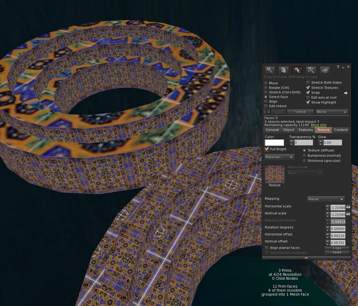
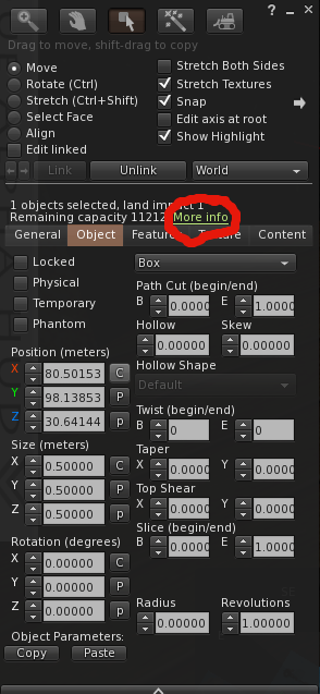
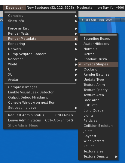
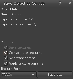
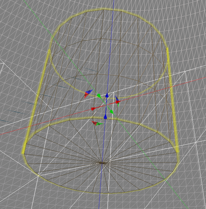
Selecting the "local mesh" option will pop up a "floater" through which all your local mesh interactions take place. Similarly to the local texture workflow, you create a list of "local" resources that the viewer will monitor. Use the [Add] button to import a DAE as you would normally; if you use properly named files the LODs will be loaded automatically too. 


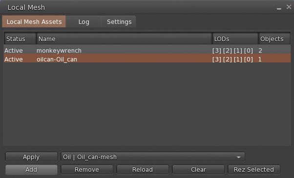
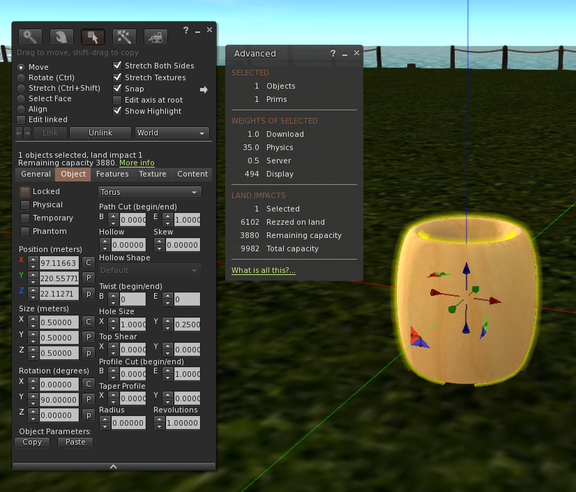
Selecting a loaded mesh from the list of local meshes, while simultaneously editing a full perm mesh "surrogate" will allow you to apply the parameters to the surrogate, making the mesh appear in your viewer. Onlookers will see only the original. You can also use the "rez selected" option to create a "surrogate" in-world and automatically "fill it" with your local mesh goodness. 

What about rigged mesh? Bet that doesn't work...

Sorry, you just lost your beer money. Rigged mesh is fully supported, with the only limitation being the need to have your own surrogate mesh (it can be any full perm mesh created by you, in fact, I often use a simple mesh cube). Attach the object and make sure it is open for editing (click on it inworld or through "edit" on the worn tab in your inventory), then just apply your local meshes. 


And yes, it even works with Animesh.

How do I update my local meshes?

The real value of local mesh is that we can now edit these and update the DAEs and quickly see the results in-world. Unlike with local textures, we do not at present auto-reload meshes, this is because the complexity of loading a collada file is far higher than that of a simple texture and for this first release it is not something we have supported. Instead, we have a refresh button that will scan all of the locally loaded mesh assets and refresh any that have changed since last refresh.

So are these just the same as real uploads?

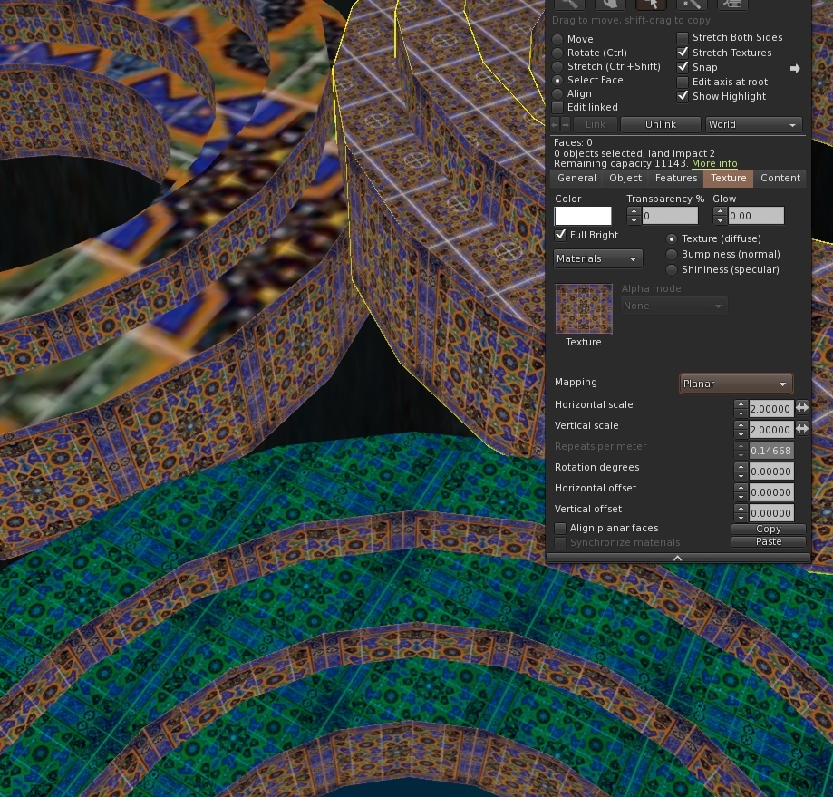
In most regards yes. You can apply textures, both from inventory or using local textures; this includes normal maps and specular maps too.


You can resize (except for rigged meshes), move them.

But...keep in mind that what you are really scaling/texturing is the surrogate object and once all this is over that object will lose the mesh override but all the other changes will remain. 

One thing you cannot do at present is link them.

OK, and this is just visible to me right?

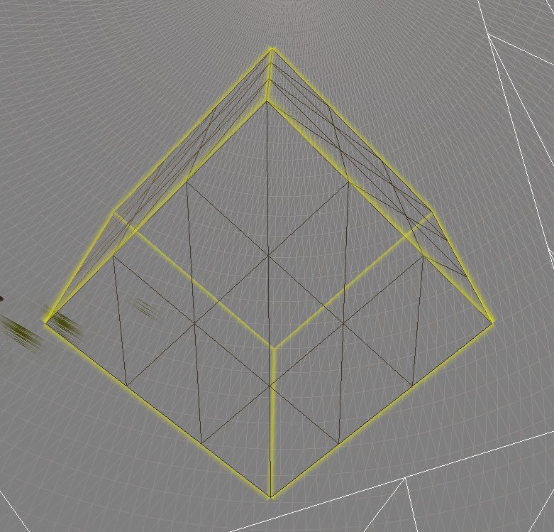
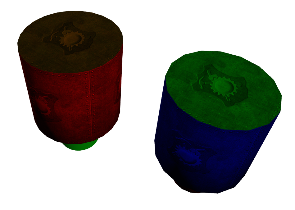
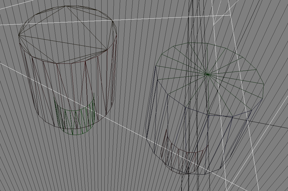
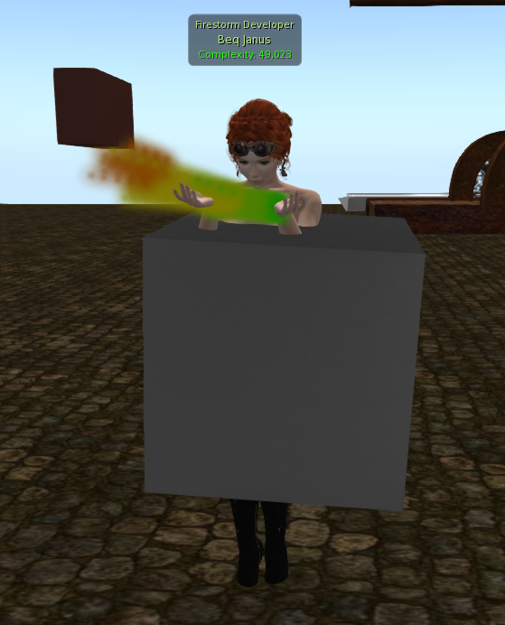
Yes, only you will be able to see the meshes, other users will see only the normal appearance of the surrogate object (including texture changes etc). This highlights another of the rough edges of this first release. The current "Rez" tool, crates a surrogate prim that will appear to other users (and yourself after a relog) as a small flat panel. In a future update, I plan to have a more concrete and visible placeholder object and ideally a way to rez directly as an attachment too. 

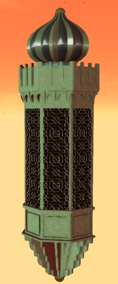
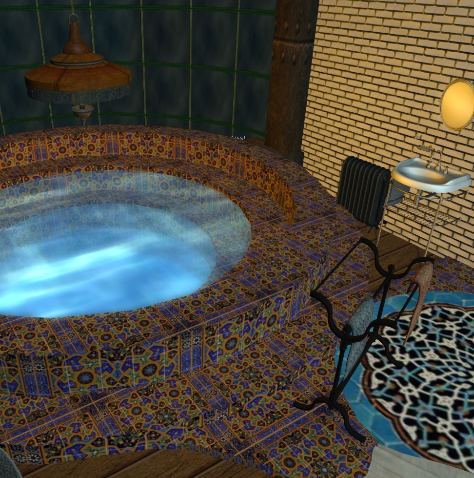
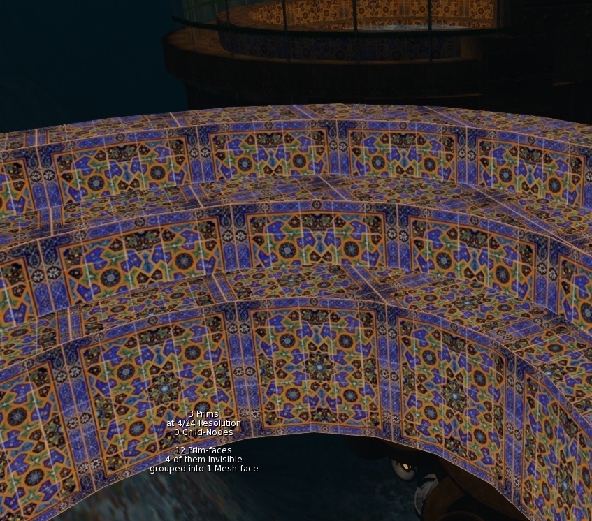
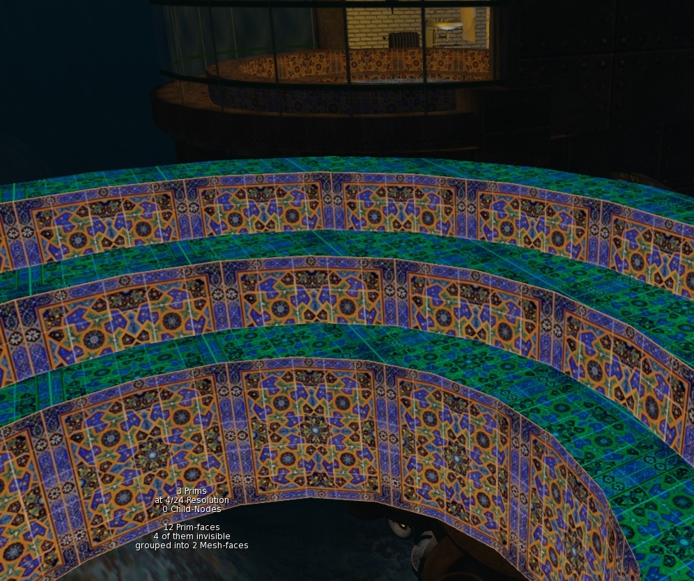
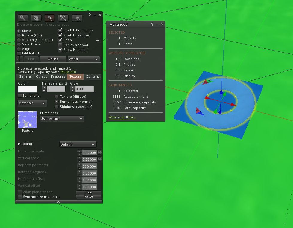
Here is what Liz could see while I was taking these photos.

I want it now... 

KK, I hear you. It's coming real soon. The new faster release cycle Firestorm should see this available to you in the next week or so. 

As of January 2023, Local Mesh is available in the official Firestorm Release. If you are on a version prior to 6.6.8, then you will need to update. 

And a final note with some background

So Beq, if you wanted this so long, why didn't it happen before?

The primary reason for this is that it requires a lot of sustained focus to get from the initial proof of concept to something usable, and as a solitary volunteer developer working in my spare time, there are always distractions, commitments and other more urgent things to address.

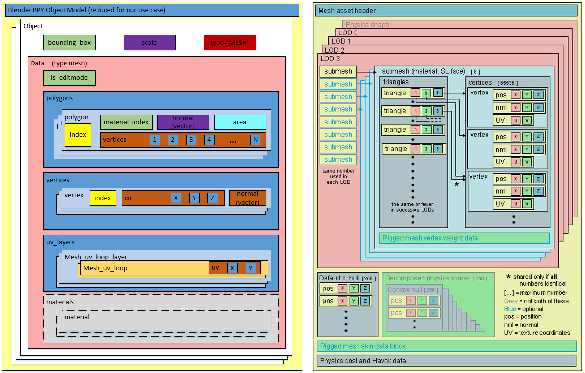
The concept b behind local mesh is simple enough once you know how mesh assets work in the viewer; you just have to create a placeholder "Surrogate" and locally "Implant" the mesh into that surrogate prim. However, as soon as you step beyond the bare basics, all the corner cases jump out and demand attention. How do we rez them? Where do we rez them? Where in the workflow should they appear, what happens if there are errors in the mesh? How do linksets work? The whole idea space gets crowded, and then a bug report comes in, or something needs updating on one of my other responsibilities, and the whole thing gets put to one side until "later". 

What it needed was someone willing to do much of that initial graft, to not get distracted by the complexities of what might be and just focus on a minimum viable implementation (MVP, yeah, I  know MVI but whatever) with no scope creep and importantly as few other distractions as possible. Early this year, that person appeared in the form of Vaalith Jinn. Vaalith (as noted above) is not entirely new to viewer development, having previously contributed the much loved "local texture" feature. When Vaalith said that they were working on local mesh, I was excited and we discussed our shared vision and where those visions differed we came to compromises and agreed on what the MVP should look like. With occasional back-and-forth discussions, the code grew to a point where, a month or so back, Vaalith presented the initial version for me to integrate. I have since tinkered with it a little to make the user interface a little more standard to FS and to incorporate a basic but functional "rez" function to place a local mesh in-world. We are now ready and excited to unleash this. 


Sunday, 20 June 2021

Summarising the next improvements to Firestorm Mesh Upload

In my last blog, I covered at length one of the changes I have put into the forthcoming Firestorm release. This post is a shorter summary of those changes and two other updates that I think will appeal to many mesh creators. 


1) Materials subset handling and related errors

For a full, blow by blow account read the previous blog, but in summary, the way that mesh "texture faces" are handled has been rewritten to give you more freedom in how your meshes are organised.

As best I can tell, there has been a bug in the Mesh upload parser (the thing that reads your Collada files and prepares them for upload to SL/OpenSim), so in-grained was this bug that most of us never realised it was a bug. We have all become accustomed to having to place empty triangles in every LOD model to represent the full set of material faces. Given a Mesh "house" whose High LOD model uses 5 materials, "frontwall", "roof", "door", "carpet", wallpaper", we might remove all the geometry from the interior faces for the lower LODs as you would never see those from the outside. However, creating "house_LOD2", as the medium LOD model with only the exterior materials present would result in the error, "Material of Model is not a subset". We would grumble that this was a subset, but with no way around this problem, dutifully return to Blender and add 2 stray triangles and assign one of the "missing" textures to each.  This is painful, time-consuming and frustrating but most importantly it is very confusing for new creators. It also has a further serious side-effect. the LOWEST LOD model is notoriously over-priced in SL, by which I mean that the cost of each triangle in the LOWEST LOD is so high as to make it near impossible and at best time consuming to produce a good LOWEST LOD model. For example, a small hand tool which due to its small size will rapidly be reduced to LOWEST LOD, can typically have no more than around 20 triangles before it starts to seriously drive the Land impact up. If you have to give away a number of these precious triangles just to please the grumpy uploader trolls then you have already lost a large proportion of your allocation. 

Form the next Firestorm release this will no longer be the case. With the exception of the high LOD model all the other LOD models can now have any valid subset of the High LOD materials, they do not even have to be a subset of the immediate parent LOD. 
Thus you can have the following structure
8 faces in the high LOD - A,B,C,D,E,F,G,H
4 faces in the Medium    - B, E, G, H
2 faces in the Low           - A, C
& just 1 in the LOWEST  - F

Or any permutation of these. The only requirement is that the superset of all materials used in all LODs must be present in at least one triangle in the HIGH LOD.

2) Ready-to-use physics presets


The physics shape tab on the mesh uploader is generally not well understood. This is in part because it is a technically complex thing, in part because the viewer has not helped as much as it could. I can't do too much about the former, though I've written a number of blogs that try over the years, the latter part I can do more with.

As of the next Firestorm release, creators will find 3 new options when selecting a physics shape.
1) The cube.
2) The hexagonal cylinder.
3) the user-defined mesh.

There tend to be two sorts of people when it comes to defining physics shapes, those that do and those that don't. For some items it is barely worth worrying about, for others it is essential. However, given that in SL it is often hard to predict how an item might be used once it leaves your protective custody, it does no harm to make sure it has a minimal physics shape that is broadly aligned to the volume of the mesh.

Many people will select the "lowest LOD", often some unrepresentative triangle. This will upload, but it means that once the item is rezzed inworld people cannot interact properly with it. A much better option for many items is a simple cube, and a lot of us keep a simple 8 vertex cube on our drives for just this. You no longer need to do this. The hexagonal cylinder is intended for items that are not quite so "cuboid".

I toyed with providing something vaguely spherical but came to the conclusion that any shape I came up with would fail to meet some need. So instead I added the ability to provide a "user-defined" physics mesh. This is a way to have a shortcut to that "shape you always use". It can be configured in the Settings tab on the upload floater. 


Some items require a custom physics shape, walls with doors and windows that you wish to allow passage through, for example. No defaults are going to help much there, but let me know if there are things that you feel would help. 

3) Ambient lighting in the viewport.

A couple of years ago, I changed the lighting in the preview window to make the three-point lighting work "better" but for some reason, things always remained dull and flat. Recently, it suddenly struck my partner Liz why this is. the ambient lighting is wrong. Upon investigation, it turned out that it was not just wrong it was "black". I have no exposed this setting on the "preview settings" tab so that you can change it, I have found a dark mid-grey about 33% grey works well and makes the lighting "pop" properly. It is especially useful when uploading with textures.

At the time of writing, there are two minor niggles that I may change before release. 
1) It still defaults to black. I considered this as a good plan but given that anyone upset by better lighting can change it to dullness again I think I will change the default to something sensible.
2) When you change the control the preview will not update until you either pan the model or reopen the uploader. I may not be able to fix this immediately.

I hope these three sets of changes improve the quality of the uploading experience for you as much as they have for me.

Take care.

Love Beq
X

Tuesday, 1 June 2021

Taming the mesh uploader - Improved workflow for builders coming to Firestorm soon

Introduction


Deep in the warren-like tunnels of the Second Life viewer code base lurk many beasts that hide in the shadows. One such beast that often shows itself at the most unexpected times pouncing upon poor unsuspecting builders, is known as the MOMINAS (Material Of Model Is Not A Subset).

TL;DR - enough with your silliness Beq, what's yer point? 

OK, the boring version. The next Firestorm should have my rewritten mesh validation that supports proper material subsets. You will no longer be forced to keep a "single triangle" placeholder cluttering up your LODs. Furthermore, two new error codes have been added to replace cases where past laziness has reused the same error code for very different issues.
Back to our tale...

The Tale Of The MOMINAS

It's a regular Friday evening at the builders' tavern, "The Prim and Proper", and many regulars are clustered around the small tables or slumped at the bar. All of a sudden, the door flies open, drawing mutterings about better door spells and smooth rotations from the occupants. A forlorn figure stumbles in from the foggy evening outside. Battered and bruised, their overalls torn and smeared with what everyone hopes is grease, the new arrival stumbles to the bar.

"Pint o' bane, please, Mal", mumbles a tired, somewhat subdued voice.  

A tankard of foaming beer slams onto the bar, accompanied by a loud chuckle.

"Blimey, someone's had a bad day of it. There ya go, get that down ya." Malcolm, the gentle giant of a Landlord at "the Prim" has seen it all in his time.

The newcomer mumbles a thank you and sips at the beer. A minute or so passes, the background babble of the pub returns to its normal levels. 

"All day! All bloody day...!" The outburst takes a number of customers by surprise and heads turn towards the newcomer again, who is staring, wild-eyed and unfocused across the bar, their arm protectively wrapped around their drink. "Fighting them, time and again, one after another. Every time I get rid of one of them, another leaps up in its place." A pause, a large gulp of beer and the newcomer turns, "MOMINAS!", they exclaim woefully, and a look of pity and recognition spreads across the assembled faces.

"They wasn't never meant to be, ya know." A cracked old voice, suggests as old Alex emerges from the shadows, ready to impart the acquired wisdom of his many years. Ignoring the questionable grammar, the newcomer turns to listen. "They's gotten too full of 'emselves ya see. Yer common or garden MOMINAS was only meant to tell you when you'd broken the laws of LOD, but they've been out o' control for years. Bad as dem MAVBLOCKs if you asks me. Prolly worse now since The Taming."

Mutterings of agreement, echo through the crowd. "Back in the day, the MOMINAS, was bred in the Lab, special-like, as a guardian to sniff out material errors in LODs that would corrupt your constructions. But "Material Of Model Is Not A Subset" to give the MOMINAS, its proper name, escaped the wards and cages of the Lab when Mesh was released and it went feral. Since then the MOMINAS has lurked in dark places, attacking lone builders without cause, spreading confusion, and worse....", the rheumy old eyes scanned the bar, flourishing his empty tankard, "... far worse...", he gave a little cough and smacked his lips, until a fresh tankard of frothing brew was thrust towards him by Malcolm. "Inefficiency!" He exploded, "it makes your stuff worse not better" the old man cackled, and a shocked hush spread,

"yes yes," he mused, toothlessly. "They was meant to make sure your LODs were aligned to the HIGH LOD. Even those first year's at the academy get taught the laws of LOD by rote; how every LOD must have exactly the same materials as the LOD above, but the laws is ... corrupted." A spray of spittle emphasises his disgust. He nods to himself and slurps his beer.

"Subsets, ya see, Sub Sets." stressing each syllable as if in the hope it would give it more meaning.  "It was meant to be that you only 'ad to 'ave a proper subset. If your house was built of Brick, Stone, Glass and Wood, then your LOD could use any mix of those, but not add Metal. A Medium LOD with no Glass should be fine. But oh no, no no no no no the MOMINAS had other ideas. and for years they's been forcing us all to think we had to have all the materials in every LOD. That ain't no subset! Any fool can see that." Banging his tankard down with a crash upon the bar as if to vanquish the monsters, the old man paused, looking slowly around as if to gauge his chances of gaining another free beer. But before he could try his luck, a voice spoke from the shadowy corner. 

"You're mostly right, old man.", said a woman's voice, its owner stepping out of the shadows. "but things are about to change." Whispers spread rapidly through the tavern, replaced just as quickly by an expectant hush."


Taming the MOMINAS

What you know is true. The laws of LOD are correct in saying that a lower LOD must use a subset of the materials used for the HIGH LOD, but it has been incorrectly enforced, probably since mesh was introduced. 
Every Mesh has a numbered list of "Material Faces" up to 8, and when a LOD is defined it must use the materials from that list. 
Thus a Cube with six materials, Red, Yellow, Cyan, Magenta, Blue and Green. Could have a MEDIUM LOD with only Red, Yellow, Green. But it cannot have Black, Yellow, Green because Black is not part of the original.  Therefore a proper valid subset of the Materials should be allowed.

However, the spells and enchantments that were woven to validate mesh (or code as some call it) is flawed and whether through the misunderstanding of the wizard that cast it, or a series of errors on their part, it enforces a full match rather than a subset.

This is bad for a couple of reasons. 
1) The underlying error code is misleading
2) Adding 6 redundant triangles to your LOWEST LOD is a costly waste of resources that limits your ability to make a good LOD model and can increase the land impact.

I have recently changed all of these flawed enchantments so that a proper subset is now supported. 
At a technical level, an empty placeholder is created for every unused material, allowing a proper subset to pass through all the validation checks unhindered by the MOMINAS guardians.

So what does this mean in practice?

If you are diligently creating your "Imposter" model for the LOWEST LOD, you will typically do that either on a dedicated material or using "Spare UV space" on another face. Historically this left you also having to have tiny triangles assigned to every other material from the HIGH LOD with these changes you now have complete freedom, so long as your LOD is a valid subset.

And there's more

Over the years, through laziness or lack of time, the MOMINAS guardian has been set to guard other, often completely unrelated problems. This has lead to a MOMINAS attack for errors that have nothing at all to do with Materials, subsets or otherwise. Other examples are:
1) No High LOD Model found - this generally indicates a more significant failure to read the Collada scrolls describing this mesh.
2) LOD model mismatch - this generally means that the matching spell, that attempts to associate parts of the LOD to the HIGH LOD, has failed to match (names are wrong, you specified the wrong scrolls etc)

These have been assigned two new guardians dedicated to their specific tasks.
Keep an eye out for other unwarranted attacks and report them to me. I can try to tame them.

How do we get these?

A new Firestorm viewer is expected to be released "soon". The QA testing period should begin soon and all being well, a release will follow that has these, and some other benefits which I'll explain over another tankard, another day.. 


Saturday, 17 September 2016

How low can you go? An optimisation war story - Part 1 HIGH LOD tuning.

Einstürzende Neu "Babbage" bauten

A bad play on words to start a long blog :-)

When I walk around my beloved New Babbage I see far too many new Mesh buildings that collapse into a garbled mess as soon as I put my settings to anything close to that of a default user. Older buildings that are sculpted I can understand but with Mesh there is not really a good excuse.

So ask yourself, are you guilty of not paying attention to the "other" LOD models?

One of the drivers towards this is keeping low LI and an assumption that creating a proper LOD model away from the HIGH LI is both a lot of work and costly in terms of LI. In this short series, we will discuss a recent project and some of the strategies I used to meet a low LI target and ensure that the object remains visually consistent but more important a viable solid silhouette at a distance. It is not going to be an all answers guide to efficient building, and I am in no way the right person to write such a thing but hopefully you will see, through my recorded pain, how you might tackle a challenging build, achieve respectable LI and preserve credible LOD behaviour.

For an older guide to creating your own LOD models, especially those using Mesh Studio, might want to take a look at my 2012 blog Too much information - making your own LOD models

About LOD and how it is observed

As the above blog explains the LOD that will be displayed is governed by the radius of the object and the distance of the observer from it. But that is not the full story; there is a multiplier that can be applied that makes the LODs appear at a higher resolution for more of the time. This setting is known as the LOD Factor (aka RenderVolumeLODFactor).

Once upon a time, setting your RenderVolumeLODFactor as high as your viewer allowed was standard practice, you can still buy outfits whose associated readme tells you to do this to maximise your experience.

The LOD factor setting was used to combat the terrible construction of many sculpty based buildings. The fact of the matter, however, is that while users of Third Party Viewers such Firestorm can set this as high as 4, the Lab viewer is limited to a maximum of 2 and defaults to about 1.5 depending on your graphics capability. It is therefore, important to consider carefully your tradeoff between more detail in the HIGH LOD and better presentation in the lower LODs. In most cases, the MED LOD is the one that people will be seeing the majority of the time.

Managing Level Of Detail is still considered a dark art by many. I see far too many Mesh builders, both experienced and new that don't understand the factors that control when LOD changes or perhaps more worryingly choose to forget that most people in SL don't touch their Advanced Graphics settings. Building with low LI is easy if you don't care what it looks like to others, however, when building for architecture, anything that is going to be seen outdoors, in particular, careful attention to the LOD levels is very important to the overall quality of your build.

What should we be aiming for?

LOD
Primary goal
Bullet points
HIGH
Close up. Full detail. This is the only mandatory model.
  • Details
  • Clean Mesh
  • Strong basic outline with finer detail.
MED
This is arguably the most important Model. It will be seen by most of the people most of the time.
  • Same strong basic outline.
  • Flatten recesses
  • Remove interior faces and anything too thin to be seen from further away
LOW
This is only ever seen at a distance, it is important that the general silhouette maintains the volume of the build to stop the "crumple" effect
  • Maintain volume
  • Focus on the silhouette.
  • Flatten all detail focus on outline only
LOWEST / IMPOSTER
The last of all. This is very hard to deal with as a model and often the imposter solution is best.
  • Maintain silhouette where possible consider using spare material slots for imposters.

An arabesque challenge

I recently undertook a request from a friend who is busily rebuilding his property in New Babbage.
He desired an arabesque bay window, modelled after a theatre in Melbourne.

"No problem", I said. "what does it look like"

The photo shows the real life bay window. The onion dome on the top is reminiscent of the onion domes that I used in Aurora - my 2014 build for Fantasy Faire no doubt one reason why the job came my way.

I often start a build in Mesh Studio but as I have been putting effort into my new workflow tools lately I decided to make this from scratch in Blender, so I set to work making an octagonal frame that I'd halve later.

I had of course forgotten two very important questions. "How big is it and how many LI do I have to play with?"

The answer came back the next day, it would need to be 9.5m high, 2m wide and about 1.5m deep,

"OK, that seems reasonable, what about the land impact budget..."

"About 2LI?"

Much teeth-sucking followed, 2LI for a large object with high detail was not an easy task.

"ookkkay." I said not wishing to give up without at least trying.

You may recall from previous blogs that the LI calculation is impacted by the scale, moreover, the issue is compounded by the realistic distance that an object will be seen from, and by whom.

If you are making a desk lamp, that will only ever be seen within your tiny office, and only ever seen by yourself, then you can take all manner of shortcuts that ignore the lower LODs and assume that the viewer has adjusted their viewer LOD multiplier etc.

In this case, though, we have a perfect storm of LOD and LI demands.
  1. Reasonably large in scale
  2. Visible from a distance as it is an external component.
  3. Seen by any visitors to the sim whose viewer settings cannot be "presumed"
  4. It needs to be low LI.
Large size means that the triangle rich HIGH LOD will be visible for a larger distance and this will put up the cost. The biggest cost is, however, going to be the MED LOD which will be visible across a very large part of the region, and thus is going to need to look pretty good.

Advice for the faint hearted

The following section *is* very long winded. It is about driving down the LI from an initial 15+ LI trial upload to the low target of just 2LI. I'll show you the working and comparisons but..

You don't need to do this to achieve results.
I find measurement is the best way to track your progress but that's just me. You can of course try these things on your objects and see how you get on without needing to measure every deatil.


Thinking about budget.

Let's do some quick maths then....no let's not, I wrote an AddOn for this...

Using a Cube of the right dimensions we find the following information

A radius of almost 5m means that our HIGH LOD model will be visible to the default user setup within 20m. Now given that this is nearly 10m high and will sit on the side of a hotel, we can assume that many users will be seeing it from further than 20m away. So as we suspected the MED LOD needs to look good. What's more, the LOW LOD will kick in at 82m. Now this is New Babbage, visibility of 82m is unheard of but we can expect people to want a viable silhouette, so we'll have to make some effort on the LOW LOD too.

We know that my plugin values for the cost are over estimating but the proportions are probably not far off. Triangles in the MEDIUM are going to cost about 15 times that of the HIGH, with the LOW costing 3 times that of the MEDIUM

In fact, we can check this using an inworld analysis script.

Radius    Total LI  HIGH LOD   MED LOD    LOW LOD    LOWEST LOD
4.968652  0.729080  0.154618   0.348042   0.216630   0.009789
LOD sizes in tris :      197         30          6          1
LOD sizes in bytes:     3536        857        476        400
Cost per tri(LI)  : 0.000785   0.011773   0.037674   0.009767

We see that the ratio between LODs at that scale is:
HIGH/MED    15:1
MED/LOW      3:1

We can also see that our budget of 2LI is going to be tough.
SL rounds down so we can creep up to 2.5.
2.5LI is 3571 triangles in HIGH LOD.
For every triangle we put in the MEDIUM LOD we must sacrifice 15 in the HIGH
For every triangle in the LOW LOD we must sacrifice 45 in the HIGH

What is more, we are working on a symmetrical Mesh, every triangle we place on one wall becomes 4 in the final mesh so our full budget per wall is 892.

Making a start

I'd started with an octagon using 3 mirror modifiers to take a single face and reflect it up into 8. The idea would be to make the octagon then slice it in two. Very quickly I realised this was the wrong path (slicing a mesh in half is always best avoided) and instead switched to using array modifiers.

The model is built to be relatively efficient. All normal first stage optimisations have been made. The two most common for me are:-

  1. Remove hidden faces.
    This applies to any mesh creating workflow, when you work in Mesh Studio you do this before creating the Mesh by setting the face to be transparent. With Blender, a similar process can be applied. MY method is to create a "fake" material face could DELETEME, assigning any that faces that I find which cannot be seen as I go, deleting them later in the workflow.
  2. Remove duplicate vertices
    As you work you often end up with overlapping mesh and blender has a convenient function to remove duplicates. It has a slider to control the threshold (how near they must be) which is great for tidying up messy joints, but it needs to be applied with care or you'll lose small details by mistake. This is also a job that can take place numerous times in a workflow. For Example, if you apply modifiers, especially mirror or array modifiers, you may get duplicates left. 

I modelled the main body, the crenellations, the dome and the lower corbel separately merging them into the joined model. The result was as follows:-


3461 Tris in my HIGH LOD Mode and coming in at around 3LI, now with the error in my AddOn we can suspect that this would be about 30% less. so perhaps 2LI, which will leave us nothing at all for the MED LOD. We are going to need to do some serious work to hit our target and frankly, I don't want to lose any of the detail I have if it can be helped.

Breaking it up - Bespoke optimisation

So what can we do? We've already done the basic stuff. We have a clean looking mesh, we removed all the doubles. So we now need to look at item specific tactics, is there anything about this object that we can use to our advantage?

If we look at the object we notice a number of things. The main body is quite plain. I modelled the fretwork for the window but only used it to generate the textures and bump maps, apart from that it is really just a few inset panels. The crenellations are far more detailed with a curved and stepped arch. Then we have the dome, At first, I reused the old Aurora dome but quickly decided to recreate it from the start, either way, it has to have smooth curves and they are costly. At the bottom end we have the curved corbel another comparatively costly piece.

By linking all of these into one we are paying the price of a 5m radius object when by separating them out we van get those same triangles cheaper. Will it make a major saving?
Let's have a look.
LOD
HIGH tris
Radius
Cost
Notes
Combined
3461
4.94
2.680
All 4 parts joined and dupes removed
Dome
787
1.58
0.062

Crenellations
1650
1.77
0.164

Bay Window
276
2.82
0.069

Corbel
784
1.65
0.067

Separates Total
3497

0.362
Notice the slightly higher tri count.

So why would we ever join the mesh? The combined mesh has a couple of things in its favour.
Feature
Joined
Separate
Server Cost
Always 0.5
0.5 for each unit. In our case 0.5 x 4 gives us 2LI Inside out target so perfectly acceptable.
Texturing
Eight texture faces
Eight faces per unit. A lot more work perhaps. Also a lot more flexibility
Upload cost
Not really sure this matters
What's a few Lindens between friends?
LOD switch
A biggy. The LOD will switch based on the BB of the single unit
The LOD will switch independently for each item. This is good and bad. It can mean that the larger features stay as HIGH for longer than the small features. All the more reason to design good quality LOD models
LOD calculation
The crux of this issue. All triangles are going to be costed at the size of the overall object. Imagine a full-scale house with a mesh door knocker.
With the parts separated into sensible chunks we pay a more appropriate price and can choose where to place out details. This has worked incredibly well on our broken up window the High LOD coming in at about 13% of the merged

So what have we achieved, so far?

We had a hard target to hit at 2LI for a large and potentially fiddly mesh. My first "sketch" was coming in at 15LI with no other LODs and that seemed to suggest a big problem ahead. But by the time we've sanitised the Mesh to just what we needed and nothing more we were down to the low single digits. 

We then made use of the fact that this object has some large flat expanses that unhelpfully push up the scale. Breaking that down we have now reduced out HIGH LOD exposure to less that half an LI. Leaving us up to 2LI (remember LI gets rounded to the nearest whole so we can go to 2.5) for the remaining LODs. 

The bad news is that because we have broken this into smaller parts we now need to consider that the LOW LOD might be seen from nearer than before and a larger budget might be needed there.

Coming soon...

Next up we will look at the MED LOD model and see how we can keep our design goals and our LI budget aligned.


Friday, 19 August 2016

It's a material world

This post is another post in my Blender Addon series. We still have some distance to climb to get to the goal of LI estimation in Blender. The Chinese have an old proverb, often attributed to Confucious that states something to the effect "the man that moves the mountain starts by carrying away small stones." With a nod to Confucious, we will carry away an armful or two of rubble today and use those pebbles to make a useful tool that was on my wishlist, a "material usage report".

Materials matter

We know from a previous blog that the Mesh that we see is not how SL sees it, instead, it expects it decomposed into a mesh per material. It is in no small part this requirement that leads to the expectation that each LOD model will share the same material set. If you try to upload LOD models that have mismatched materials you will get an error such as this

The nasty yellow "Error: Material of model is not a subset of reference model" is the bane of a Second Life Modellers life, if you are anything like me, that is. Typically this occurs for one of two reasons; the first is that you've just messed up the materials, and you have a mismatch, that is easy to spot (it may or may not be easy to fix). The second reason is the one that, for me at least, is far more common. You've diligently optimised your model, removing all the internal faces that won;t ever be seen at a distance, simplified those pillars and struts and somewhere along the way you ended up with a material that is in the model but has no actual mesh associated with it. 

Looking in Blender will show the full list of materials that were used, you'll need to go through each in turn to find out which of them is actually empty. 

Gien that our grand tour will require us to cross this small hill on the way to the summit we may as well deal with it. We need to parse our object into materials before we can go much further, so let's count the polygons in each LOD as we go.

In Blender the mesh data has a list of polygons and each entry in this has a pointer to a material index the refers to the "material_slot" of the parent object. We can, therefore, write a short set of routines that will process the models that we have, building on the previous work that allows us to associate objects together as the LOD models and produce a composite report on the materials used by our LOD models and any errors that we find.


In my first stab at this, I used the material_index to build the map, and it worked perfectly because the model I was testing against had the correct material slots. When I tested with the object used to create the error above the report showed an issue, but it was not the right issue.

The curved window section above will be featured in another post, one on mesh optimisation and the lower LOD models are not complete because they (deliberately) do not have the same materials, but of course they do all have index 0. It is not the index that counts it is the material inside and given that the materials are kept per object, we need to use the name, not the index.

Having corrected that bug, we now find that we can reproduce the error from the SL uploader in Blender but provide more information to the user at the same time.
As you can see here, we are still able to show that the High and Medium LOD models are using the same subset of materials but that the LOW and LOWEST are not, what is more, the LOW and LOWEST are in fact using a completely disjoint set of materials, as evidenced by the warning sign in the high and medium LODs.

This is a contrived example to some extent, this is a work in progress and I knew it would not upload but hopefully you can see how the tool has saved a round trip of export and upload. 

Another example

We have used a dome object I have built in the past in previous examples and so I will illustrate how the tool can quickly pin point a material issue and save time.

The first image shows the HIGH LOD model and the report is flagging up an issue with the "glassinner" material in the MEDIUM LOD.

Now we see that the MEDIUM model has the slot in place, so it is not simply that the material is not there. We have to drop into edit mode to uncover the truth. While we were deleting all the interior mesh that would never be visible from in the MEDIUM LOD range, we accidentally deleted all of the  "glassinner" and so it is no longer matching the parent. So we can now assign a single triangle in the mesh to this material and it will fix the problem.


One last note, in the final report here on the left,  the LOWEST LOD (denoted as X due to the L for LOW) is marked as - and not an error.

This is because we have not defined a LOWEST LOD model in Blender and it therefore assumes that you will be generating this upon upload and it does not need to worry about it. Therefore, exporting the HIGH, MED and LOW objects and then importing them wil not give us any material based errors.
I think that these tools are now starting to offer value and if a few people are interested in becoming beta testers for me then I would love to hear from you. Contact me inworld or through Google+ from this blog.

As always, if you find this interesting or think it would be useful to someone please +1, share, whatever else. A typical blog entry here gets about 20 hits, I'd love to reach more people but only if what I am writing is useful.

Love
Beq
x


Monday, 1 August 2016

Mixing planar and non-planar faces in Mesh Studio

Something for the Mesh Studio afficionados today.

Mesh Studio has a "feature" insofar as it does not detect the mapping mode of a prim face. This results in an incorrect Mesh import later. First, a quick illustration of the issue and then how to fix it.

It is time to do a little more work on a slow burn project to gradually rebuild parts of my ancient underwater home. I've only got half an hour to spare so I want to Mesh the steps in the moonpool, so that I can safely apply some materials without it blowing up.


I quickly copy the existing object, tossed in the joined mesh script, eliminate a couple of the unnecessary surfaces and hit "Mesh".


A few moments later and I have it imported, apart from being a few Lindens poorer, we are good to go,aren't we? I drag the texture onto the Mesh and....ugh! That was a waste a Lindens, the texture UV mapping is wrong.

 A quick check of the source model and the reason is clear. While MS quite correctly noted that the texture UUID and the tint are the same on all the faces, it failed to note that top faces were planar mapped, while the inside cylinder faces were default mapped.


Happily, this is easily fixed. All we need to do is convince MS that this is a different face to the other one. We can do that by changing the tint value. A quick lick of paint and we find that MS now correctly sees this as having two mesh faces. and we are ready to splash another few lindens on an upload.


Rezzing the newly uploaded mesh we gleefully drop out texture on it and for a moment our hearts skip a beat. It still looks the same. Then we remember, it's called "default" mapping for a reason and sure enough highlighting the face and setting the mapping mode to planar snaps it back into shape.


And so there we have it. When mixing planar and non-planar with the same texture just make sure that they have a different tint.

If you have a larger build that will be painful to convert manually I have written a script that runs through the material list, identifies clashes and auto-magically changes the tint. Ping me an IM inworld and I'll send you a copy until I get around to putting it up to download somewhere.

I'm heading out for a couple of weeks so take care and more blogs when I return.
For now, I'll close with a quick recap of the steps with some materials applied to give the tiles that glazed shine.A bit overdone but mission accomplished for the Mesh at least.

Love

Beq
x


Saturday, 30 July 2016

Blender mesh data deep dive.

It's been a while since we last had a post on my quest to write better workflow tools for Second Life Mesh creators using Blender. In the last of that series, we took a long hard look at what exactly was meant by download cost and why our naive triangle counter was giving us such overestimates. Now it is time to try to use some of that knowledge to see how we can build that from Blender.

Decompression sickness

It was the compressed byte stream that was throwing out our numbers and, as a result, we will need to reproduce the data and compress it to find the byte streaming cost. This means that we need to look at how the polygons are stored in Blender.

We did a little of this when we were counting the triangles but we barely scratched the surface. 
All the data we need is in the bpy.data structure for a mesh object.

The BPY data structure is not very well documented but there is a lot of code around and the excellent blender python console that lets you try things out and features autocomplete.

Given an arbitrary mesh object (obj) we can access the mesh data itself through obj.data

import bpy

obj = bpy.context.scene.objects.active # active object

mesh = obj.data
Within obj.data we have access to a list of vertices and a list of polygons and a vast array of other attribute and views on the data.

Following in the footsteps of the wonderful visualisation of the SL Mesh Asset Format by Drongle McMahon that we discussed in a previous blog I have had a stab at a comparable illustration that outlines the parts of the blender bpy data structure that we will need access for our purposes
On the left, we have my "good parts version" of the BPT datastructure, while on the right we have the SL Mesh Asset visualisation from Drongle McMahon's work.

We can now start to list out the differences and thus the transformations that we will need to apply
  1. SL Mesh holds all the LODs in one "object". We have multiple objects, one per LOD.
  2. A Mesh object has a list of polys that index into a list of vertices. SL has multiple meshes, split as one per material face
  3. SL only accepts triangle, we have Quads and NGons as well.
  4. Each submesh is self contained, with triangles, UVs, normals and vertices listed. Vertices are thus duplicated where they are common to multiple materials.
  5. SL data is compressed
So let's sketch out the minimum code we are going to need here.

For each Model in a LOD model set.
    Iterate through the polygons, and separating by material
    For each resulting material mesh
        for each poly in the mat mesh
             add new verts to the vert array for that mat. mesh
             adjust the poly into triangles where necessary
             add the resulting tris to the material tri array
             write the normal vector for the triangles
             write the corresponding UV data.
    compress the block

Having done the above we should be able to give a more accurate estimate.

A lot easier said than done...Time to get coding...I may be some time.

Love

Beq
x


Sunday, 24 July 2016

When is a door not a door? And other things they should have told you about physics

There are a couple of features of Mesh physics that come up time and again in group chat. They are the, "oh yeah, *that*, didn't you know about that?" type issue that makes building, or learning to build in SL an "adventure" at times.

The first one goes like this:

Eve: Help, I just returned my housemate's things.

Fred: Did you cut up all his shirts first?

Eve: no no, I was just sprucing up an old build on my platform and lots of things got returned.

Gloria: What do you mean "sprucing up"?

Eve: I have this, old hat I made years ago, I just modernised it by adding some bump and shine.

The second one, starts like this:

Andrew: OK, so I've done all the usual things and I cannot walk through my door.

Brian: Try opening it?

Cathy: set the physics type to prim

Andrew: Yes yes, done all that. It makes no difference. It's a bug in the uploader maybe? I have a wall, The physic shape looks fine in the preview.

This can run on until Andrew loses his cool... For now, though, we'll take a look at Eve's problem.

Physics accounting and the small thin triangles.

In the last blog entry of my Blender Addon Series,  we covered the Mesh asset format and looked briefly at the physics section. We learned from that that there are a few possible ways that a Mesh can convey its physical shape.

  1. A single convex hull. A mandatory shape for any mesh
  2. An additional decomposition of up to 256 hulls, each consisting of up to 256 vertices.
  3. A mesh designated for use by the physics engine.
More details of these can be examined on the Mesh Physics wiki page which has a lot of technical details that we will use in a future blog. For most people, if they specify a mesh model they use a low poly mesh and do not use the analyse button. This typically results in a lower physics cost but herein lies the problem.

Mesh physics shapes

By default when you provide a mesh shape for the physics, the viewer will encode this and upload it. Importantly, however, the physics resource cost is only estimated for the scale that you upload at. If you rescale it in-world it will change the physics cost. This may not surprise you, after all, the streaming cost increases as the size of an object increases, so why would the same not apply to physics? But, in what may seem an odd choice, the physics cost decreases with scale and gets larger as the object shrinks.

So why is this? It ultimately comes down to the cost of tracking objects.it is far more costly to track hundreds or thousands of tiny triangles that really don't add any perceivable value to the accuracy of the shape detection so in order to discourage such behaviour the Mesh accounting algorithm penalises mesh physics for the use of small thin triangles

Eve was only using prims, so why does she care?

Prims have the dubious quality of being capped at 1LI when subjected to traditional accounting. This grossly under-represents their true cost in terms of rendering and lag but the internal physics cost is still calculated and you can see this using the "more info" button on the build/edit dialogue.


As you can see here the effective physics cost of the humble 0.5 0.5 0.5 torus is 35LI but due to the cap it is only showing as 1LI.

But it is not limited to 35LI. Because the physics cost is driven by scale and the "width of the triangles" compressing a shape massively provoke the physics cost.The next few images demonstrate the results of some minor torturing of a Torus.
By compressing it vertically we lift the Physics to 88.6

By making it long and thin we drive it up to a scary 910.7, but we aren't done yet
With some carefully applied torture incrementally path cutting, twisting etc. we can achieve a sim filling, sandbox burning, home destroying 9313.8 LI
Consider the above if you have legacy objects that consist of many tortured prims.
 If this were, however, only limited to the "hidden cost" this would hardly be a problem at all but it is not.

Unconstrained prims on the loose

When applying the cap to legacy prims, Linden Lab drew a line under what had gone before and protected it, thus avoiding breaking existing content. However, that rule does not apply to new features being applied to old content deliberately. 
There are two ways of breaking the cap. The first, perhaps most obvious way is to switch to modern "Mesh" accounting by changing the physics type to "convex hull". This can be done accidentally by linking a prim against a Mesh item. It can be pretty dramatic on a domed building or something with a lot of curved surfaces. 

All that glitters is not gold

The second way is more subtle and for the most part less well known and that is to apply a material to the prim. Materials were added a couple of years ago and provide for user defined bump (normal) and specular (shiny) maps. They are one of the quickest ways to modernise a drab looking older build, but they have a hidden surprise, as the moment that a material is applied to a prim it will switch to mesh accounting and reflect its "true" physics cost. 

It is this that Eve stumbled into in the mock scenario above. applying a spec map to an old prim necklace consisting of tortured prims is a great way to very quickly fill your parcel.

So take care when applying materials and linking legacy prims to modern items. You would not be the first person to find that a significant amount of damage has been caused.by an inadvertent ctrl-L

Damage limitation.

As mentioned above, the equation used to determine the physics cost divides by the width of a triangle. The mathematicians amongst you will already have realised that this means that the cost goes asymptotic as the width approaches 0. The 9000+LI that I managed to generate may not be the highest you can get (though it is the highest I have managed to drive a prim up to) but it is more than enough to do significant accidental harm accidentally. To limit the damage the viewer applies a simple constraint to save us. If the dimensions of the prim's bounding box go below 0.5 then the viewer will ignore the physics mesh provided and instead collapse to a simple solid convex hull. An example of this can be seen in the following image where our, previously 35LI, standard torus has been shrunk beneath the limit and now has a physics cost of just 0.1
.

and this brings as back to the question we started with...

When is a door not a door? When it's a hull.

and back to poor Andrew and his wall without a doorway.

Emily: Have you double checked the physics type?
Andrew: yes it's prim. I've done all the usual things, I've run out of options.

and so it goes on

Many times the cause of the issue will be resolved by asking one question.

Me: Andrew, What are the dimensions of the object?

Invariably, the response will be

Andrew: 20x4.5x0.1, I hate thick walls.

Inadvertently, by minimising the wall thickness Andrew has triggered the hull physics, blocking his door and ensuring it will never open. At this point ,Andrew has two options. He can either scale the x or y dimension to make the wall thicker (this is always the best test that this is the correct issue) or he can use the analyse function to produce a multiple hull based physics model that is not affected by scale and does not have the limiter applied. In general, the analysed physics costs more.

Summary

When you specify a mesh physics and don;'t analyse it, or when applying modern features to legacy builds, you open yourself up to physics issues. That can be summarised in a couple of rules
  1. Don't shrink any object with a physics shape without paying careful attention
  2. Don't apply a bump or spec map to a prim build without checking  for side effects.
It has a safety valve that can itself cause issues. Which can be summarised as:-

If your physics shape is set to prim, you are sure it looked right in preview (or metadata - see below). Check that no dimension <0.5.

Both sets of issues are resolved by using "analyse" but be aware that this frequently comes at a higher (fixed) physics cost.


A post script - One last tool in the physics armoury

If the scaling does not fix it then you'll need to prove whether the physics exists where it should.
One mistake that can be common with custom physics shapes is not ensuring that the BB matches that of the object. 
A tool that is specifically designed for tracking down physics issues can be found in the developer menu. (Note: the developer menu can be enabled from the viewer preferences.)
Go to the Developer->Render Metadata-> Physics shapes and tick it. The world will turn mostly blue.

The blue parts are physical surfaces, and, in fact, they are "heat mapped", an object with a very high physics cost will appear progressively orange and then red. More importantly, if you line the object you are inspecting, up against the skyline, you can see the areas that are not blue and which ought to correspond to holes/doors/windows. If the bounding box of the physics model does not match that of the LOD models then it will have been stretched/compressed to fit and any non-alignment will now be clear.

One word of caution when using this, however. There is a metadata display bug (at least that is what I consider it) that means that for Mesh objects, the mesh physics shape will be displayed even when the size restriction means that the default hull physics is being used. The convex hull shape can be seen when "convex hull" is explicitly selected, but will not show when it is being used because of the size limit. Interestingly this is the exact opposite of the behaviour I reported two years ago, so perhaps the change that addressed that problem fixed that and broke this?


Friday, 22 July 2016

What did Mesh Studio ever do for me?

There have been a few reliability issues with the Mesh Studio servers of late and this has led to much grumbling from the beleaguered users.Mesh Studio is one of a number of inworld Mesh creation tools that allow you to generate Mesh directly from prims. Other tools, such as Mesh Generator, work in a similar fashion (with a similar price tag) but for me MS is that most flexible and easiest to use. But what exactly is it that MS does for us?

I've seen a few articles on the web about the mesh saving/export capability of Singularity, that was later adopted into Firestorm, often they will say things such as "I really don't see what Mesh Studio does that "save as" does not. This blog will demonstrate the key differences.

The problem with "save as"

Save as can be found on the Pie menu in Firestorm (I can't comment on other viewers). The image below shows where it is. For Mesh, always pick "collada".

We can then "save as". The default options such as "skip transparent and "apply texture params" should be used.


We can then "save as". The default options such as "skip transparent and "apply texture params" should be used.

The "save as " function literally exports the mesh of the object, it does nothing more. The one exception being the very useful "skip transparent" which will not generate mesh for any faces that are set to be fully transparent. 

The result for a simple cube is a Mesh analogue of the following inworld image.
As you can see our cube is divided up somethig akin to a rubik's cube puzzle with each straight edge defined by 4 vertices. When theses vertices are triangulated it results in 18 triangles per side, or 108 triangles per prim cube. In most cases, splitting a straight edge makes no real sense. and results in extraneous vertices that add to the overall complexity of our object. Similarly all circles, be they parts of a cylinder or a sphere, are defined as 24 straight edges. By extension a quarter cylinder wedge has its curved edge defined by 6 straight lines.

In the image above we see a standard Second Life cylinder prim. The fan of triangles on the bottom shows us the 24 sides of the circular edge and then as we look along the straight sides of the cylinder we start to see the multiplying effect of that "4 vertices per straight" default. as our cylinder now has 24 slices, each consisting of two triangles, multiplied by three, plus another 24 triangles in each of the end caps, a total of 192 triangles. This is not a massive issue if you are using the model as HIGH LOD model and letting the importer generate the lower detail models for you. However, in a build of any reasonable complexity, if you want it to look good you will probably need to make at least a MEDIUM and probably a LOW LOD model. At this point you are going to pay a very high price for those ineffectual extra vertices.

The other, arguanly the largest limitation is that when exporting a linkset, every prim in the link set is exported as a separate mesh object, wrapped in a single .DAE file. Why is this an issue? It is probably exactly what you want it to do, if your objective is to export a prim build as-is but if you intention is to reimport as a mesh then the way that mesh uploads are accounted for has a word or two to say.

As we know, from other blogs I have posted, the mesh accounting has 3 components and the overall effective LI the larger of the three. For the most part we care about the streaming cost and the physics cost, the final member of this triad, the server resource cost is capped at 0.5 per mesh unit on upload (it can change inworld) . The key words in that previous statement are "per mesh unit", If you have a 32 PRim build that you are going to turn to Mesh, and you use "save as", if you do nothing else it will cost at least 16LI as each of those 32 units will be charged 0.5LI.

Mesh Studio to the rescue

Mesh Studio (MS) allows you the option to export things in many other ways. You can control the number vertices in a straight or circular edge, you can ask it to weld all the prims in a linkset into a single mesh object. It supports the "skip transparency" option that we saw in the "save as" but extends this to allow 

We can now use our model to generate the Mesh that we want at a complexity that is sensible. In general I never use 4 for straights, I have not found any good reason for it yet. The curve setting is very useful allowing your to make smoother curves that SL default for your high LOD model and then drop to a coarser 16 and even 8 sided curve for low LOD levels. 

To get an idea of how I tend to work with Mesh Studio, you can watch my timelapse clock building video found on my Vimeo page.

"But Mesh Studio servers are down and I really need to get this Mesh finished."

The downside of the in world mesh creation tools is that they depend upon external scripts to perform the mesh conversion if for some reason they are not available then the Mesh creation process will fail. 

I hear a lot of people complaining about this when it happens, about how their business depends on it etc. and frankly I don;t have an awful lot of sympathy for that position. If you have a business that is important enough in terms of revenue that a day or a week of delayed production is critical then you need to have a backup plan. 

You have two real options. The first is to use another inworld service and hope that they are not both impacted at the same time. One slight drawback here is that (as far as I have been able to tell) the functionality of MS is not fully available in any other product, the nearest is Mesh Generator but it does not support a number of advanced MS features such as linked sets or more crucially, arbitrary definition of the complexity (that ability to set any value for the number of circle segments), Mesh Generator in this case does allow changing it but only to pre-defined values.
If anyone is able to correct my understanding here please contact me inworld, as my experience is only through the limited documentation and the demo version.

The second option is to use an off world tool. Choice of these tends to come down to personal experience and in some cases biases but it is also largely about budget. Maya uses swear by the power of their tool, but unless you have access to a student version it is going to cost you of the order of 2000 USD (possibly per annum?). At the other end of the spectrum is the phenomenally powerful, but ever so slightly (very) scary, Blender. 

A lot of people find Blender to be impenetrable, and it can be daunting especially if you are used to the very simple and friendly in world tools. However I would suggest that a few very simple commands that most people can manage to memorise will allow you to get close to the same quality of Mesh that Mesh Studio will output, starting from a "save as" output.

To demonstrate this I recently made a very quick and dirty video.

The video shows me importing a 110(ish) prim model that I had hoped to generate am MS output from. I guide us through joining all the objects together (bringing the LI down from 55 to 7) and then cleaning up all those extraneous vertices.

So does that mean I don't need Mesh Studio now?

What I hope it has shown you is that Mesh Studio saves you a reasonable amount of fiddling around. It may only have taken a few minutes but consider that you need to do that for every iteration if your source model remains the inworld version. Every time you change the model you will need to clean it up. But there is another issue, that of UV mapping. 

Both MS and "save as" do a pretty good job of exporting the UV mapping of the textures, What is less clear is whether that editing survives the clean up process.I most cases I tend to remap the UVs so it is not an issue for me, however I did conduct a test and both the Mesh Studio model and the Firestorm Save As model survived the cleanup commands as shown in the video.
The image above shows the MS export on the right (exported at 16 sides per circle) with the FS save as export on the left. Both were cleaned up using the same method, however, the MS mesh did not have a limited dissolve applied. The net effect of this is that it retained the triangular fan on the cylinder top while the FS export has a rather uglier geometry.

In summary

By using Mesh Studio you automate a number of mesh optimisations that you might otherwise have to do when operating on a round trip workflow from Prim to Mesh. By performing these operations reliably and repeatably in world it makes the process more efficient and of course, for many simple items allows an immediate reimport of the Mesh at a considerable LI saving.

I hope this helps some of you to have a look at how Blender or similar tools can help you out in a fix, but also serves to remind you that the 20 dollars spent on MS was a pretty good investment.

Love 

Beq
x